
Weekly Assignments
One of the main deliverables of Fab Academy is to document the progress; what I do, how I did it and what I have learned.
In the assessment guidelines it literally says "Imagine that one day you need to reproduce all of your assignments. You have no internet, no-one is able to help you. You have only your Fab Academy archive folder and the resources within the Fab Lab. Ensure that you have documented everything in enough detail in your archive so that you can do this easily." So that's what I'm going to do; I'm will document my learnings like there was no tomorrow ;)
Week 1: Principles and Practices
assignment: plan and sketch a potential final project
A toy for kids
My initial idea for my final project is to create a toy for kids, to learn from, and interact with. A goal of mine is to start a preschool in Sweden at some point, and I would like to make a toy that could be used there, and elsewhere. I want kids to explore and learn from experiences. I want kids to not just be consumers of technology, but also producers.
Ingrid the Tiger and Ebbe the Bear
Interactive building blocks
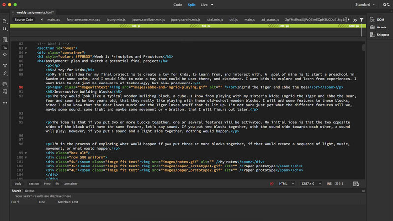
The toy would look like a typical wooden building block, a cube. I know from playing with my sister’s kids; Ingrid the Tiger and Ebbe the Bear, four and soon to be two years old, that they really like playing with these old-school wooden blocks. I will add some features to these blocks, since I also know that the Bear loves music and the Tiger loves stuff that is lit up. I’m not sure just yet what the different features will we, maybe some sound, some light and maybe some movement or vibration, that I will figure out later.
The idea is that if you put two or more blocks together, one or several features will be activated. My initial idea is that the two opposite sides of the block will have the same feature, let’s say sound. If you put two blocks together, with the sound side towards each other, a sound will play. However, if you put a sound and a light side together, nothing would happen.
I’m in the process of exploring what would happen if you put three or more blocks together, if that would create a sequence of light, music, movement, or what would happen.
 My notes
 Paper prototype
 Paper prototype
Who is it for?
This toy is for all kids, mostly targeting kids around the age of two to four, that like to build things and explore possibilities. The toy could possibly enhance the kid’s logical thinking and stimulate their different senses. The explicit advantages of this toy are still to be discovered.
Material
I want the main material to be some type of wood. I believe it's a fun material to work with. It looks nice too and it's many times a better material for kids compared for example plastic. I don't know yet what components I will use, most certainly some type of battery, electronic connector and some magnets or similar to connect the blocks to one another.
Inspiration
I got inspired by my local instructor Emma Pareschi’s final project from back in 2014. I especially like how she integrated the electronics into the wood and the small holes she made for the light.
 The electronics in nicely integrated into the wood
 The electronics
 The wholes for the light
I also got to see a project from some time back when the blocks were connected using magnets and with a thing (a name I don’t know yet) that connected the electronics between the blocks.
 Magnets to connect, electronic connector in the middle
 Connected
 The inside
Week 2: Project Management
assignment: build a personal site and upload it to the class archive
My first website
I have built one of the first websites of my life. This time without using a content management system and instead only code and pushing it from Git. I did use a template from Bootstrap to help me start, but I have been altering the HTML to explore new possibilities.
Installing Git
First I installed Git. Git is a distributed version control system meaning it’s “a form of version control where the complete codebase - including its full history - is mirrored on every developer's computer.” (Wikipedia)
Connecting local repository to GitLab
Since Fab Academy are using GitLab, a web-based Git repository manager, I had to connect using an SSH Keys, which allows me to use the Git repository in a secure way without using a password every time. I followed Fiore’s tutorial and got help from friendly Henk.
I generated the ssh-key:
$ cd ~/.ssh
$ ssh-keygen -t rsa -b 4096 -C "johannan.nordin@gmail.com"
I edited my ssh config file and added
Host gitlab
Hostname gitlab.fabcloud.org
User git
Identityfile ~/.ssh/fabacademy-gitlab
IdentitiesOnly yes
And then I changed the “git@gitlab.fabcloud.org” to “gitlab”
I set up my identity
$ git config --global user.name "Johanna Nordin"
$ git config --global user.email "johannan.nordin@gmail.com"
And then creating my first repository
$ git clone gitlab:academany/fabacademy/2018/labs/fablabamsterdam/....git
$ cd johanna-nordin
$ touch README.md
$ git add README.md
$ git commit -m "add README"
$ git push -u origin master
To make sure everything was set and to know which remote repository was tracked by my local repository, I used the git remote command
$ git show remote originAnd then I got to see all the details:
* remote origin
Fetch URL: gitlab:academany/fabacademy/2018/labs/fablabamsterdam/...
Push  URL: gitlab:academany/fabacademy/2018/labs/fablabamsterdam/...
code>HEAD branch: master
Remote branch:
master tracked
Local branch configured for 'git pull':
master merges with remote master
Local ref configured for 'git push':
master pushes to master (up to date)
In GitLab I later added the file .gitlab-ci.yml to make the repository viewable as a site. This was a specific file for this occasion so I followed Fiore’s instructions and copy/pasted the content.
Using terminal
I wasn’t that familiar with Terminal before. To be honest, when I was watching my first Git tutorial I had to google “What is the terminal on Mac”. I, of course, felt a bit embarrassed, but I guess I can’t be the only one starting from Zero.
Creating the actual website
I started out locally on my computer, just because I was worried that I would mess up the Fab Academy repository. I created an index.html file and started from there. I used Atom as my source code editor, which I have tried before. I soon moved to Adobe Dreamweaver that I heard was even better. I picked a template from Bootstrap to help me get started. I didn’t really think things through when picking the template; the Clean blog template doesn’t really suit my needs, so my site is a bit messy at the moment.
After playing around a bit locally in a different folder, I decided to add my files to my local repository (connected to the origin master) and make my first commit.
It went well. I had some trouble, I didn’t read what Git told me, so I messed up a few times before it finally worked. Here you can see a video of my first (second, and third) real commit.
HTML
w3schools.com explain HTML very well; HTML is the standard markup language for creating web pages. HTML stands for Hyper Text Markup Language and describes the structure of web pages using markup. HTML elements are the building blocks of HTML pages, and they are represented by tags. HTML tags label pieces of content such as "heading", "paragraph", "table", and so on. Browsers do not display the HTML tags, but use them to render the content of the page.
For learning HTML I went through a few tutorials. I did a few classes in Codecademy and I used w3schools.com for some help with specific elements. For me, learning basic HTML has mostly been about googling. I learned about the difference between HTML, JavaScript, and CSS, when to use what and an overview of how it works. The elements that I mostly use is making headings, lists, paragraphs, add pictures, links, etc.
The commands
The most common commands that I used altering the template and making this site is the following. I will not write the symbols since that would make Dreamweaver think I'm writing HTML code.
- p - Paragraph
- h1-h6 - Heading
- li and ul - Unordered List and List Item
- img - Image
- iframe - Embed another document, for example youtube
- div - Division
- span - A container for content inside a paragraph
- a href = "document location" - Link
- !-- -- - Comment. Anything between these tags is not displayed on the screen
- br - Line break
- header - Introductory content for my page
- nav - Navigation content, my menu
- main - Main content of the web page
- footer - Footer of a page
- html - Opens and closes an HTML document
- head - Pprovide information about the document
- title - The title of document
- body - Contains all the content
 Code for sections, divisions, lists and headings
 Code for paragraphs
 Code for one type of picture section
JavaScript and CSS
JavaScript is the programming language of HTML and the Web. CSS is a language that describes the style of an HTML document and how HTML elements should be displayed. CSS stands for Cascading Style Sheets. CSS saves a lot of work since it can control the layout of multiple web pages all at once (w3schools.com).
I didn't do any changes in the JavaScript, but a few in the CSS-file that came with the template. I changes the colors and added the new background picture. To do so, I checked what hex color code the template had, and replaces that number with the number for the mustard yellow color that I wanted to use.
This is how the template looked before I made the changes. The biggest change is that I added more pages to the site; having seperate pages for Home, My Story, Final Project and Weekly Assignments.
A new look for the website (added 14th of Feb, 2018)
So what you can see now is the new look of my website. This time I used HTML 5 UP for my template, I used this one called Read Only. I have also made a lot of changes in the CSS file this time. Making new formats for showing pictures etc. The main reason for changing template was the menu. I find this menu, not perfect, but better suited for my needs.
Week 3: Computer-Aided Design
assignment: model (draw, render, animate, simulate, ...) a possible final project, and post it on your class page with original 2D and 3D files.
Simple 2D design in InDesign
2D in InDesign
I made a very simple sketch of the cube in InDesign, showing how the cube would be hollow on the inside, keeping all the electronics inside the cube. I decided to keep it very simple since I still don't know what components I will add to my cube.
Now in retrospect, I should have used Adobe Illustrator instead of Adobe Indesign. The two software have man similar functions, InDesign is a vector based program, however, InDesign's strengths really lie in its ability to handle multiple pages and create master pages. Illustrator is also a vector based program, meaning unlike photoshop which is rastor based and uses pixels, Illustrator uses a mathematical grid to map the artwork that is created, therefore all artwork created in Illustrator is scaleable, resizeable without losing quality. However, since my design is so simple, it doesn't really matter this time. For the file to be useful for machining, I exported the InDesign file as a PDF. I then opened it in Illustrator and exported it as an DXF file that could be used for machining.
I used the "Line tool" and the "Rectangle Frame tool" to create my design. I changed the solid line to be dotted on the lines that you wouldn't see from looking at it.
Fusion 360
I had barely any experience in 3D software before this week. I have played around in Tinkercad with the kids during Hyper Island Kids Summer Camp last summer, but that was about it.
On Thursday we had a full day workshop in Fusion 360 with Mauro Jannone. Fusion 360 is a 3D CAD/CAM design software, free for students, educators, and academic institutions. During the lecture I had some problem understanding the software; why we did what we did, and why the specific order of things. Also the linguistic was fairly new to me.
After the lecture I've been playing around in Fusion 360. I also watched this tutorial to get a better understanding of the software.
Designing a possible final project
Since I don’t yet know how my final project will look and work, I decided to make a design of how it will look from the outside, not spending time on the inside of the cube.
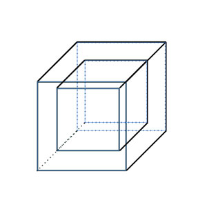
To start a new sketch click “Sketch”, “Create new sketch” and then select the plane you want to work from. If you, for example, want to create a rectangle, click “Rectangle” and select what type you want to draw. To set the measurement, just type in the numbers you wish. If you wish to make a parametric design, click “Modify” and then “Change Parameters” to set the measurement.
To be able to make a sketch on your model is really useful. To do that, just click “Create Sketch” and then click the plane you want to start from. You can also choose to have an offset from the plane.
You can use shortcuts for different commands, “L” for “Line” for example.
Another useful command is “E” or “Extrude”. The command that can either cut, join or intersect a body.
 First sketch
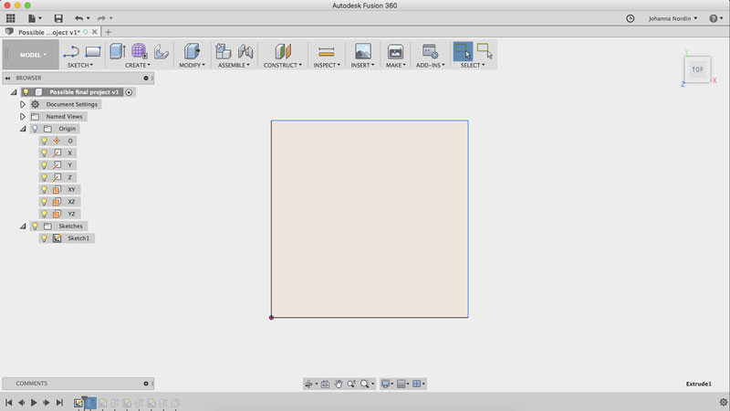
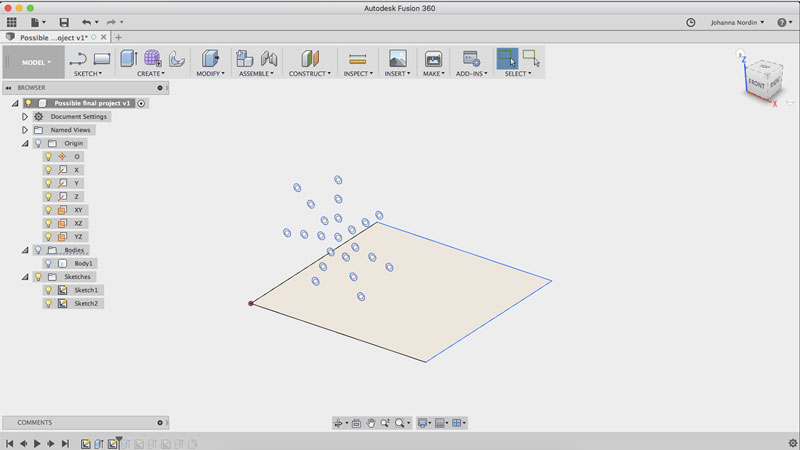 Second sketch on side plane
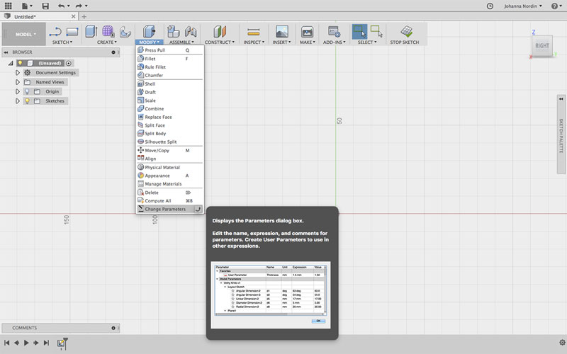 Change Parameters
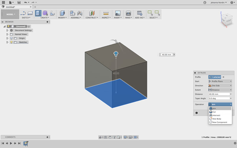 Extrude
“Circular pattern” and “Rectangular Pattern” is two commands that duplicate sketch curves, in a circular or rectangular pattern.
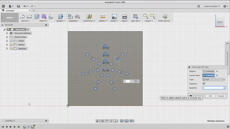 Making circular pattern of one row of circles
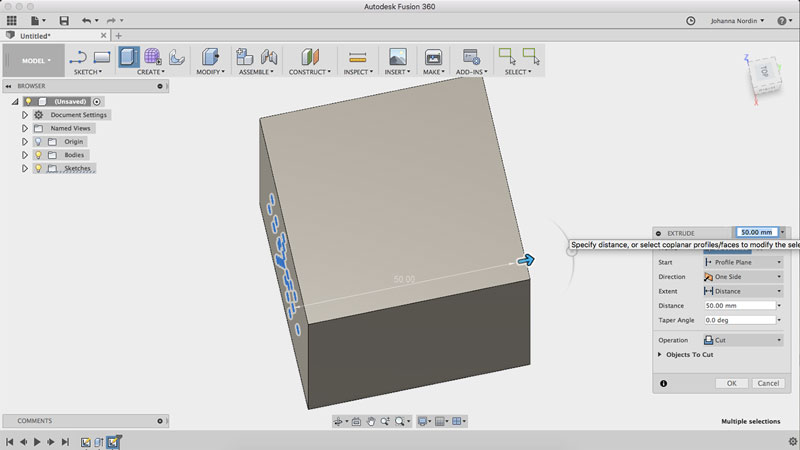 Extrude circles (cut) over to other side
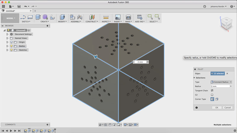 Making the edges a bit more softer with fillet
Render
I decided to render the model a bit, having it look like it's made of oak. To do so, I changed “Workspace” to “Render”. Under ”Appearance” you can change the appearance of the model, just drag and drop the different material to your faces or bodies. After that I did a “In canvas-render” making the finishing to the appearance.
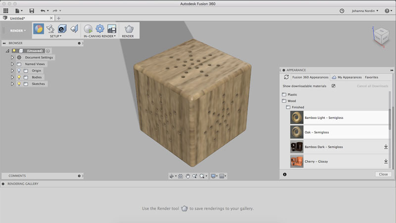 Pick material in appearance
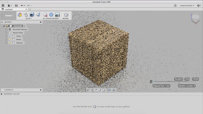 In canvas render in process
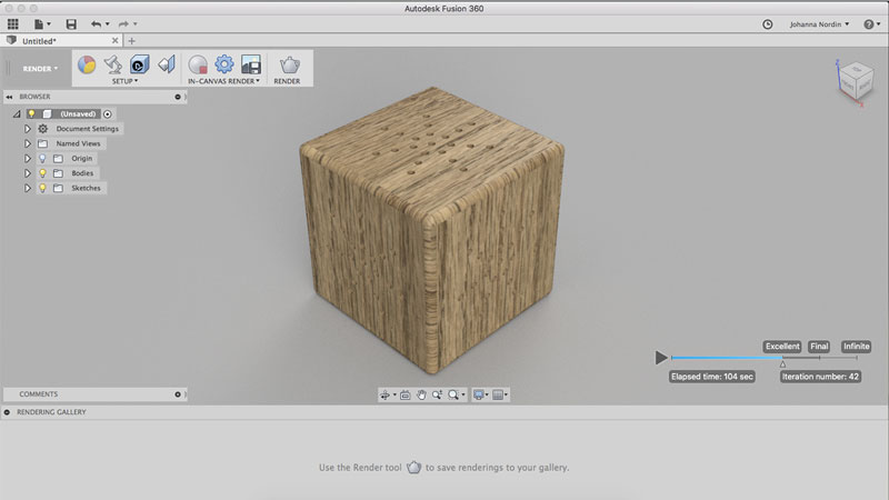 In canvas render in process
3D CAD
One part of this week’s assignment is to try different tools. I downloaded FreeCAD, an open source parametric 3D CAD modeler and watched this tutorial on basic functions. I don’t really like how FreeCAD structure functions. I have a hard time understanding what button does what. I will play around some more to get a better understanding.
Download files here
Possible final project STL
Possible final project f3d
2D model in InDesign
2D model in DXF
Week 4: Computer-Controlled Cutting
assignment: 1) cut something on the vinyl cutter, 2) design, laser cut, and document a parametric press-fit construction kit accounting for the laser cutter kerf, which can be assembled in multiple ways
This was a really fun week! I made a lot of progress, at least in my head :) I also made a lot of mistakes, which was probably the most fun part.
To give an overview. I started out making a press-fit construction kit. Parallel I was working on a laptop case that I would print in MDF material. Both of these I sketched in Fusion 360 using parametrics.
I also made stickers, one easy one with my name on it, and then I went ahead and made a tiger and a bear for my niece and nephew.
My first press-fit construction kit
Fusion 360
I made my first ever press-fit construction kit. I decided to start “easy”, but it wasn’t that easy to me. I used Fusion 360 for creating the sketch. Since I’m not yet friends with Fusion 360 since last week, I was a bit worried, but it worked out fine with some help from friendly Frank.
Sketch
I started off adding the parametrics, since this was going to be a parametric design. I went to “Modify” “Change Parametrics” and then I typed in the numbers I wanted. I will get back to which numbers I chose below. I made a sketch; a circle and a rectangle. I created a few constraints; that the circle should be “tangent” to the end of the rectangle, the rectangle “horizontal”, and the center or the rectangle “fixed” to the center line of the circle. I used the tool “Circular pattern” to create the rectangles spread out even around the circle. The sketch was done. I right clicked the sketch icon and “Save as DXF”.
 My first sketch in Fusion 360
Adobe Illustrator
I instead used Adobe Illustrator to make the final changes to the design. I altered the “stroke weight” to “0.1 pt”, and the “shape builder” to only keep the actual lines that I wanted to cut. I had to ungroup the shapes och delete the extra ones. I copy/pasted the shape three times to cut more pieces to my kit. Done. I exported the file to DXF.
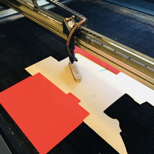
Lasercut5.3
Then it was time to laser cut. I had saved my file on a USB. I opened Lasercut5.3, the program our Fab Lab used for the machine. I imported the file. My shapes were huge! I resized the shapes, only the vertical and made it proportional since I had four pieces laying next to each other. I downloaded the design, telling the machine what to cut.
I now know two different ways for the design to stay the same size. Make sure the measurement in Illustrator is mm, not pt. Also, I don’t need to export a DXF file for the laser cutter, I can just use my Illustrator file (Illustrator CS6 for this machine).
I had a look in the cutting journal, looking for 3mm cardboard that was cut perfectly. I found:
Cut:
- Speed: 150
- Power: 90
I kept corner power to 20% and overlap to 0.05. The corner power is the decreased power the machine use doing corners since too high power might cause cut off corners. The overlap is the mm of overlap the laser goes around your cut, making sure the piece is cut off.
In the software, different colours represent different settings, that the user choose. Since I was only going to cut, I picked black and selected cut and my prefered settings.
To pick the origin of the laser, I went to the menu “Set laser origin” and then “left top”. To test the origin I later did a test when the machine was on.
I went to the menu and clicked “simulate” to see how the laser would go. I downloaded the file to send it to the machine, I clicked “delete all” so no other files where to be left in the machine, and then upload current.
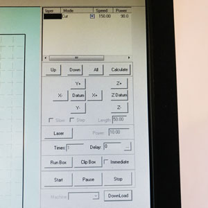 Settings in Lasercut5.3
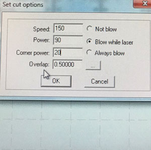 Settings for speed and power (not this cut)
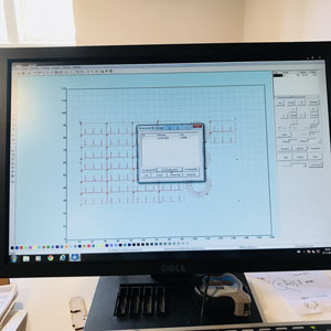 Lasercut5.3
The machine, a BRM Lasers 120160 - laser cutting my first own thing
I placed the cardboard on the laser bed. I moved the laser by using the arrows and placed it close to the end on the cardboard. I calibrated the laser to make sure the distance between the laser and the material was good, using the wooden measurement that comes with the machine. I did a test to make sure I was going to cut in the right place. The test was fine - so now time for the actual cutting. No fire and no accidents - my pretty design were created.
 Measure the distance between the material and the laser
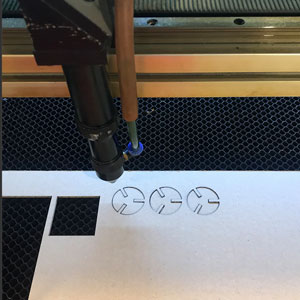 Cut!
Cut!Safety
Apparently all Fab Labs have had a laser cut fire. I don’t want to be the one causing one. It is very important the the ventilation system is on at all times when using the laser. When the cut is done, turn off the laser tube and open the door to the bed. Then smell - very important, and also very enjoyable due to the nice smell of burned wood/paper. Keep the ventilation on for a while. There is a red line around the laser cutter which you are never supposed to leave when you’re cutting - a sneaky way to have your classmates make coffee for you, hint David. There is also an emergency button to stop the machine, and always water close by.
First try
I made a simple sketch, using some parametrics bot didn’t account for the kerf or really thinking about how far in I wanted the slots.
- Circle diameter = 30mm
- Slot length = “circle diameter/3”
- Material thickness = 3mm
The slots was to long so when assembling them, they couldn’t fit together. And the fit wasn’t tight enough.
Second try
I changed the length of the slots to ⅕ of the diameter for all to fit together. I did also account for the kerf that I had measured using a test on cardboard earlier on.
Parametrics:
- Circle diameter = 30mm
- Slot length = “circle diameter/5”
- Material thickness = 3mm-kerf
- Kerf = 0.175mm
The slots were now fine, but the fit wasn’t 100%. I then noticed that the cardboard I was using wasn’t 3mm as I had assumed, but 2.76mm.
Third try
I changed the material thickness and this time it worked really well.
 My parameters for the third try
 First try
 Second try
 Third try
Chamfers
Later on I added "chamfers” to my design, so the slots could more easily slide in. In my sketch in Fusion 360, I added 2 lines, going from the center of the rectangle 45 degrees. I then made a “Circular Pattern” to apply to all slots.
 My sketch with chamfers
 A close-up on the chamfers
Looks like a cactus, right?
A full on press-fit construction kit
As easy as it might look, I believe Ingrid the Tiger and Ebbe the Bear will love playing with these. So I cut a whole bunch plus made some simple longer shapes so it can be constructed in different ways.
I almost nailed a laptop case on the first try. Almost
I have seen designs using “living hinge” and I wanted to try that. A living hinge is when you cut the material in a way that you can bend it. I decided to do a laptop case. I used Fusion 360 and I made it parametric.
I must have been tired when measuring my laptop, because I made the length too short. However, since I made my living hinge a bit too flexibel, my laptop could still fit. I will make some alterations to the sketch and try again soon.
The design
I have seen a few different box designs; different amounts of slots, different length of the slots, different type of lid etc.
The one I made had many slots on the bottom of the box and just three to hold the lid in place when closing.
 My sketch of the laptop case
 Close-up
 My parametrics
Since this was my first go on a more complex design, I decided to cut it and try it, before going into too many details. For example, I didn’t account for the kerf, and the MDF thickness was varying in different places, from 3.07 to 3.14mm and I accounted for 3mm.
Simple kerf test
Even if I didn’t account for it in my first try, I did a simple kerf test. Before cutting my design, I made a 10x10mm rectangle and cut that, also to test the settings of the laser cutter.
I had a look in the cutting journal, looking for 3mm MDF that was cut perfectly. I found:
Cut:
- Speed: 40
- Power: 100
I kept corner power to 20% and overlap to 0.05.
I cut the rectangular and measured it across. It was 9.74mm meaning the machine had cut away 0.26mm. Since the machine cut on two side, the kerf equals 0.26/2 = 0.13mm.
I should also mention that when I first made my living hinge, I wasn’t sure how much I could alter the pattern. I downloaded a pattern from Obrary, I used the “Straight 1.5mm” since I thought the tighter the better. Using the same proportions as the pattern sketch, I ended up having only three “pattern parts”. Emma, my local instructor saw the design before printing and recommended me to squeeze more in and make the area of the living henge wider. So I did, but too much.
When cut, the living hinge became a accordion. It might not be that I had too broad hinge and too many pattern part, however, I should have added more pattern parts on the lengths of the pattern, not just adding more to the width, but also to the length.
The rest of the laptop case turn out ok. The press-fit wasn’t tight enough, witch I knew since I didn’t account for the kerf and the side of the laptop case was too short, which must have been a measuring mistake.
I will alterate my design and cut it again soon to see if I can make a perfect laptop case.
 Looks alright, but you can tell it's too short on the hinges
 Looks like a accordion
 And too short
Kerf, cutting and engraving test
Me and my classmates made a few kerf test. We also tested the power and speed for cutting and engraving different materials. For speed and power we looked in the cutting journal.
Cut 3mm cardboard:
- Speed: 150
- Power: 90
- Kerf: 0.175mm with simle test cutting a 10x10mm rectangular, dividing the cut by 2 (2 cuts)
- Kerf: 0.27mm with the test cutting 9 pieces and measuring the space cut away, divided by 10 (10 cuts)
Cut 3mm MDF:
- Speed: 40
- Power: 100
- Kerf: 0.15mm with simle test cutting a 10x10mm rectangular, dividing the cut by 2 (2 cuts)
- Kerf: 0.18mm with the test cutting 9 pieces and measuring the space cut away, divided by 10 (10 cuts)
Cut 3mm Acrylic:
- Speed: 20
- Power: 100
- Kerf: 0.15mm with simle test cutting a 10x10mm rectangular, dividing the cut by 2 (2 cuts)
- Kerf: 0.18mm with the test cutting 9 pieces and measuring the space cut away, divided by 10 (10 cuts)
We also made a engrave test, using different power and different speed. In this test the speed was always 350, but the power 40, 60, 80 or 100.
 Kerf test cutting 8 pieces
 Measuring the space was hard
 Engraving test
I made stickers - Tigers and Bears!

Joey sticker
But first
But before I got to make Tigers and Bears, I decided to start easy and make a sticker with my name. I also did it directly in the computer that is connected to the vinyl cutter at the Fab Lab, which made it even more simple. In Illustrator I wrote my name. I marked the letters and clicked “Object” “Expand” to make the letter wider and with a path. I changes the color to see through “Fill” and black “Stroke” I changed the thickness of the “Stroke” to 0.1 pt. Ready to cut!
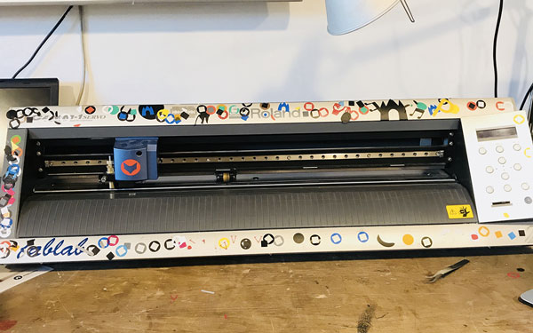
The machine Roland
I loaded the material, a role of vinyl to the back of the machine, securing it with the two locks. I inserted the blade in the blade holder. I changed the amount of "blade extension", i.e how much the tip of the blade extending from the blade holder. I wanted to make sure the blade would go through the vinyl but not through the underlaying material.
The menu in this machine is not really user friendly, it’s hard to know where to go and why. But by clicking around I got to pick if I was using a role or a piece of vinyl. Furthermore, I set the origin of the blade; pressing "origin" till it flashes on the display. I set the "blade force" to 90 gf and "speed" to 5 cm/second, and I did a test. The test is done by pressing "test" for 0.5 seconds or more. The test was fine.
 Roland
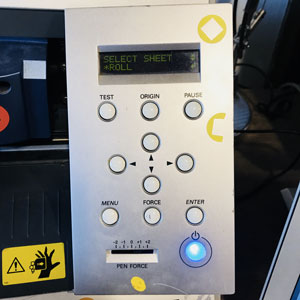 Select roll
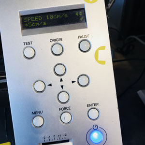 Select speed
Back to Illustrator
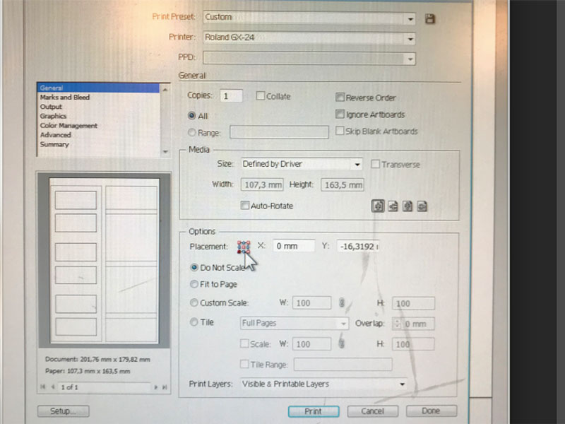
To cut vinyl from Illustrator I just used “Print”. In the settings it’s important to choose "Cutting Area” to “Get from machine”. It is also important to pick the placement of the design to let the machine know where the design is. And then print.
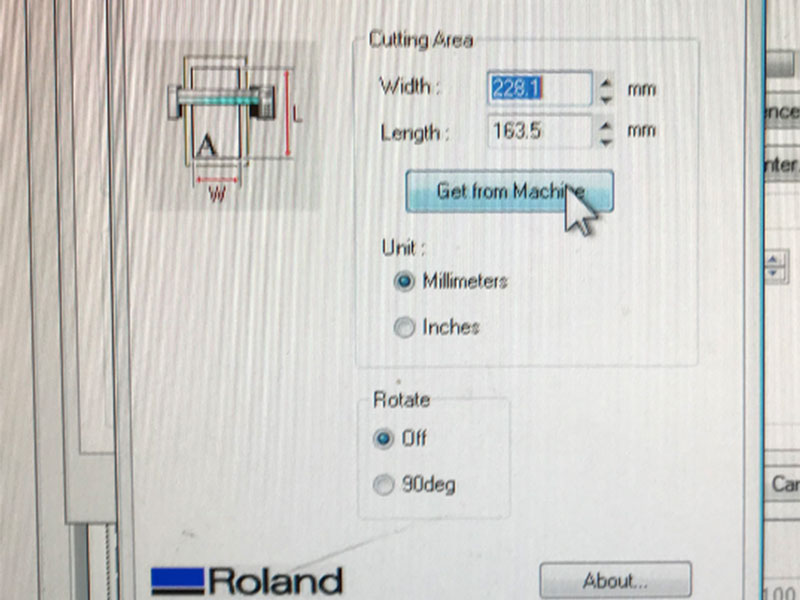 Get from machine
 Cutting Area
Tigers and Bears
I downloaded the emojis of the tiger and the bear and alterated it it Illustrator. I cut away parts and added a few to make lines thicker. I used the tool “Image trace”, then “Expand” and then I changed the “Stroke” to 0.1 pt.
 Original bear
 In Photoshop
 In Illustrator
It might sound easy now but I had some trouble on the way. First I made a too detailed design for the size of the sticker I wanted to make. I also had some problem with double lines which made the machine angry and it messed up my design. What I ended up doing was just making sure I had no double lines just before cutting. With this type of construction in Illustrator, I had no idea where all the lines was coming from.
 Double lines made this
 The tiger and the bear
 Nicely looking on my computer
Manage the sticker once it's cut
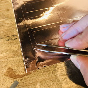
The process of getting the sticker off the vinyl is fairly easy if you use tweezers and the tape-like material that you transfer the sticker onto. First, peel off the part that is cut off; the vinyl around the sticker and the parts inside that is cut off. Take some of the tape material and attach to the front of the sticker. When you want to place your sticker in a place, peel off the backside and attach it. Make sure all bubbles are taken away. Then take off the tape.
 Tweezers (picture from another occation)
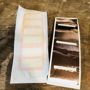 The tiger and the bear
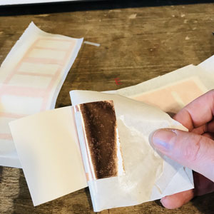 Nicely looking on my computer
Download files here
Laptop case.fsd
Laptop case.ai
Laptop case.dxf
Press fit construction kit.ai
Link to Tiger and Bear ai
group assignment:
assignment: characterize your lasercutter, making test part(s) that vary cutting settings and dimensions
Week 5: Electronics Production
assignment: make an in-circuit programmer by milling the PCB, then optionally trying other processes
It's easy when you know what you're doing
This week’s assignment it to make an in-circuit programmer. I didn’t even know what that was when starting this week. An in-circuit is short for integrated circuit and that is simply any type of circuit, made to fit into a chip. It can be called a chip, a microchip or an IC. A programmer is the hardware that can conduct the process of transferring a computer program into an in-circuit. A PCB is a Printed Circuit Board; in this case, a board made of composite epoxy, with conductive pathways of copper that has been etched or "printed" onto the board, that can connect different components (wikipedia). So if I understood it right, I'm making a board, downloading software to it so that it can later program other boards, i.e a programmer.
The whole process of cutting and tracing the board is pretty simple. But of course I took the opportunity to mess up so I had to practice the process twice. ;)
Roland MDX-20 milling machine
Set the machine and board
At the Fab Lab we have a Roland MDX-20 milling machine. To prepare the machine I first cleaned it from leftovers from earlier projects. In this assignment we use a one-sided copper board. I chose to wash my hands and the board before getting started to minimize fat and dirt on the board.
I used double-sided tape to attached the copper plate to the bed. I have learned that you should press it onto the bed really hard to make sure its not tilting. Also not to overlap the double-sided tape since that also could make the board tilt.
Hold the end mill so it doesn't break
I pressed the button “View” on the machine to change my 1/64 in end mill that I would first use to do the tracing on the board. I untighten the screw and placed the end mill. I made sure only the black part of the end mill was visible. I held my finger on the end mill so it wouldn’t hit the bed and break. And I also didn’t tighten the screw too hard, since it’s not needed and it will be hard to change later. I went out from view mode by clicking “View” again.
The software
At our Fab Lab we have a computer connected to the milling machine. In the Linux operating system we have a shortcut to a Fab Lab program called Mods In the software I click “Programs” and then “open server program”. As “file to open” for this assignment we click Roland, mill, MDX-20, PCB. What opens up is a process of transforming a png file to something that can be read by the machine and cut. For this assignment we had a ready made pgn for traces, I used Brian's.
In Mods, there is two processes to choose from; mill traces or cut. Just like when laser cutting, it's good to mill first (engrave for laser cutting) and then cut to keep the board stable.
I clicked on the button “Mill traces” and I used the default setting for mill traces. Set PCB defaults:
Mill traces (1/64)
- Tool diameter (in): 0,0156
- Cut depth (in): 0.004
- Max depth (in): 0.004
- Offset number: 4
Mill raster 2D
- Tool diameter: mm: 0.39624 in: 0.0156
- Cut depth: mm: 0.1016 in: 0.004 (first cut - enough to cut away for traces, not when cutting trough)
- Max depth: mm 0.1016 in: 0.004 (deep at the end)
- Offset number: 4 (0=fill)
- Offset stepover: 0.5 (1=diameter)
- Direction climb (not conventional)
- Path merge: 1 (1=diameter)
- Path order: forward (not reversed)
- Sort distance (yes)
- Calculate the path - click button calculate
I clicked calculate for the program to calculate the png and the settings. A new tab opens with the path.
 This is how Mods looks
 Path for tracing
 Path for cutting
Roland MDX-20 milling machine
- Speed: 4 mm/s
- Origin x=10 y=10
- Jog height: 2 (how high the mill goes when its moving)
Prepare the machine for tracing
In the software I need to set the origin. I tested the origin x=20 y=20. For the machine to respond to this I had to open the communication between the computer and machine. On this computer we have a shortcut, (serialserver.sh) and by clicking that, then “Run in terminal” a terminal window opens saying “listening for connection from client…” Back in Mods in the box “serial server” click “open” status change to “serial port opened”. Now the machine and the program was connected.
That placement of the end mill wasn't correct. I change the origin and tried x=15 y=17. Hard to see where the end mill was since I wanted to reduce the use of material so I made it really close to the end of the copper. So I move the end mill down with the button on the machine. I didn’t dare to go that close, so it was still hard to see, I had about 2 mm to spare. So I changed the origin to x=20 y=20 again to then calibrate the end mill. What that means is to set the distance between the end mill and the copper. I move the end mill down by using “down” on the machine. The reason is that you don’t want the end mill to far out since that can cause vibrations when its running. I loosen the screw, held the end mill with two fingers so I wouldn’t drop it and break it. I made it touch the copper and I rotated it to make sure there were no dust between the mill and the copper. And then I tighten the screw. Now the calibration was done. Then I changed origin to x=15 y=17. It looked good.
I need to update the file since I changed the origin. I need to recalculate the path by clicking “calculate” again. I put the cover on the machine and then I clicked “send file” which starts the machine.
When the tracing was done I use a brush and I vacuumed the bed to take away the material that had been cut away.
Cutting off the board
I have to change the tool to cut out the board. I use a 1/32 in end mill for the cutting of the edge. I had to repeat the calibration. I pressed “View mode” and then I changed the origin to x=0 y=0. I did this because when I move the end mill at this point, it will go down since I have done the calibration for the other setting that I just ran. So if my tool is too long, it will cut the copper and maybe brake the end mill. I then moved the end mill up using the button on the machine. After that I went back to my old origin, x=15 y=17. Now I can do the calibration again. I press the end mill down and turned it a few times, and then tighten the screw. The machine was now ready to cut.
I upload the new file for cutting. I clicked “mill outline (1/32) since that was the process I wanted to preform. I got the default setting and I clicked calculate. Set PCB defaults:
Mill outline (1/32)
- Tool diameter (in): 0,0312
- Cut depth (in): 0.024
- Max depth (in): 0.072
- Offset number: 1 (this is the number of lines, I only have one line so I kept it to one)
Mill raster 2D
- Tool diameter: mm: 0.79248 in: 0.0312
- Cut depth: mm: 0.6096 in: 0.024 (first cut - enough to cut away for traces, not when cutting trough)
- Max depth: mm 1.82879 in: 0.072 (deep at the end)
- Offset number: 1 (0=fill)
- Offset stepover: 0.5 (1=diameter)
- Direction climb (not conventional)
- Path merge: 1 (1=diameter)
- Path order: forward (not reversed)
- Sort distance (yes)
- Calculate the path - click button calculate
Mill outline (1/32)
- Roland MDX-20 milling machine
- Speed: 4 mm/s
- Origin x=15 y=17
- Jog height: 2 (how high the mill goes when its moving)
It was then ready to cut.
My cut didn’t go the whole way through. I probably put the speed roll to low. I had to repeat the calibration. My biggest mistake was that I didn’t look if it cut the whole way through when it was still on the bed, I removed it. So when I wanted to place it back, there was no way for me to do that perfectly in the same spot. So I ruined my board. And I had to start all over again.
New origin
- x=15
- y= 37
My cut-out board
This time I forgot to press “mill outline” so it was cutting the cut as a trace. I saw this when going to “view mode”. To start again when I had changed the settings, I had to press the “up” and “down” button at the same time to reset the machine.
I started cutting again. This time I checked if it was cut the whole way through before taking away the bed. It was!
I then cleaned the machine and washed my board with water and soap.
The components
For this assignment we are making a board that a former student Brian did. I followed his tutorial to see which components I needed. I collected them all and wrote their name on a paper.
 I collected all my components
To get an idea of which one to solder first, I placed them on the board. I had a look at the schematic and the board image Brian made to get the component values and placement. The ATtiny85 is the most difficult part. The ISP header I will solder last as it is large and might get in my way.
The ATtiny85 has a dot on it. It’s important that the dot is in the same place as the dot on the board image. Same goes for the diodes since they have a orientation.
Soldering
I turned on the soldering iron to 70 (Fx10). I cleaned the iron by melting som tin on it and cleaned it with a spunge.
I stared soldering. My hands were shaking even before starting. It didn't make things easier. If you are good at soldering, the tin is supposed to be smooth and shiny. I managed to make a few of them. If a component has many “legs”, it's good to first attach the component by first melting some tin to one of the plates fastening one “leg”, and then solder the other “legs” of the component. Sometimes I got too much tin on the board, then I used desoldering copper wire to take it away.
The last step was to create a bridge on the jumper. Apparently this connects VCC to the Vprog pin on the ISP header so that the header can be used to program the tiny85. Im supposed to remove this bridge later to turn the board into a programmer.
Shorts
When I was done soldering I checked the shorts by using a Multimeter. I turned on the sound alternative and place the two on different parts. I made sure Ground and VCC wasn’t connected. I check the shorts to the microcontroller. Emma checked if her programmer could see my microcontroller. I inspect my board just by looking at it; the components wasn't super flat onto the boart, but it worked so I guess it was fine.
I attached some double-sided tape and some thicker paper to make my board a bit thicker and fit better into the port.
Program the ATtiny
Then it was time to program my programmer. I downloaded this software. The software runs from the terminal.
I used Emma’s programmed board to program my board, connected to each other and placing Emmas board in my computer.
The rest of the process was very hard to understand. And apparently we were a few weeks ahead of schedule doing this, so this week it was ok that I just followed Brian's tutorial and not really understanding what I did.
In short. I downloaded a folder and opened it in Terminal. I used the command “make” to build the hex file that will get programmed onto the ATtiny85, the file “fts_firmware.hex.“. I updated the “Makefile” because I was making a tiny85, not a tiny45 which was pre programmed.
I used the commands: “make flash” to erase the target chip. Then I ran the command “make fuses” that set up all of the fuses (except from one).
 Make flash
 Make fuses
To test my USB on the board, before blowing the fuse, I unplugged it from Emma’s programmer and plugged it in to my computer.
My computer registered my board
I opened ”About this Mac” in the Apple System Profiler, the ”System Report”. I selected USB and I say my USBTiny listed as a device. I did this multipel time to make sure it was working properly.
After that I blew the ”reset fuse” to make my board into a programmer that can program other boards. I ran the command "make rstdisbl”.
What I didn’t do which was part of the tutorial was to remove solder from the jumper, Emma told me to leave it for now.
Now I had my very own working ISP programmer!
 My own in-circuit programmer
Download files here
group assignment:
assignment: characterize the specifications of your PCB production process
Week 6: 3D Scanning and Printing
assignment: design and 3D print an object that could not be made subtractively and 3D scan an object
3D printing
The assignment of this week is to 3D print something that could not be made subjectively, meaning more or less, print something that can’t be done with the other machines. I decided to make a fairly simple design that I have been wanting to test for a while; a sphere inside a square.
Fusion360
For designing the print I used Fusion360. I made a sketch of a rectangle 50x50mm and then extruded it and made it into a cube. To make the spheres inside the cube, I used the function “Construct” “Midplane” to create two planes to place the two spheres on.
The first sphere I made bigger than the cube itself and selected the operation “cut”. This made the holes in the cube. Then I created a smaller sphere that I place inside the cube, this one with the operation “new body”.
The design was ready and I exported it as a STL file.
 A cube with two planes
 First sphere
 Second sphere
Cura
I imported the file into Cura. I had the Cura 2.5.0 version from before on my computer. In Cura I selected all the settings for the printer. I clicked Ultimaker 2+ which is the printer I decided to use.
I went for the default settings, but did a few changes that would speed up the printing time.
- Nozzle: 0.4
- Material: PLA
- Profile: Fast print
- Print Speed: 60mm/s
- Travel Speed: 150mm/s
- Shell, Wall Thickness: 0,7mm
- Shell, Top/Bottom Thickness: 0,75mm
- Infill: Light (20%)
- Enable support: Yes
- Build plate adhesion: Yes
The temperature among some other settings for the material can not be set directly in Cura, but in Ultimaker 2+. 3dverkstan, a company in Sweden that I have been working with before have a great tutorial on how to create custom material profiles.
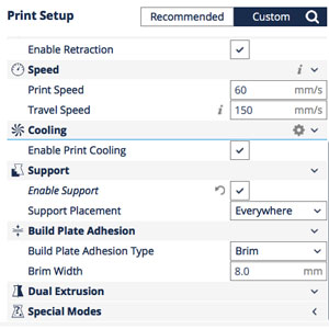 Settings in Cura
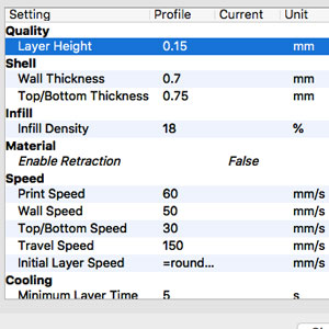 Settings in Cura
 Before changing the settings the print would take four and a half hours
 Then barely two hours
I went into custom settings and changed the Layer height from 0.15 to 0.20. This makes the Layers “thicker” hench the print faster.
 Layer height to 0.20
I changes the size of the design by changing the “Scale” to 75%.
 Scale it down 75%
I decided I wanted the design to have two different colors, but Ultimaker 2+ only takes one at the time. Friendly Frank told me this was possible by pausing the print and changing the colors. To do that in a more controlled way than just pausing the print, I used the setting “Extensions” “Post Processing”, “Modify G-Code” then “Add a script”. I picked “Paused at height” and changes the settings to pause halfway. I also added 128 “Extrude amount” since that is recommended when changing material.
 Settings for Pause at height
 For every print there is also code/text. Here's the code for my pause
In inserted the SD card in my computer and exported the file. The print was, according to Cura, going to take approximately two hours.
Ultimaker 2+
First I had to load my first material, white PLA. I turned on the power on the machine. Selected “Change material”. I place the material on the back of the machine and cut the PLA 45 degrees, which is apparently good to make the material a bit more friendly when extruding. I clicked the menu so the material started to heat up and come out. First some green PLA came out; material that was used before me, and then my white PLA. I stopped the machine and took away the material that was not going to be used. I clicked “start” and my design started to print.
 Ultimaker 2+
 After a few minutes of printing
 Print halfway
Halfway the machine stopped and I changed the material to black PLA. Then I clicked “resume print”. After two hours my print was done. No big mistakes had been done during the printing, only at one point I took away some of the support that had misplaces for some reason.
Clean up the print
My design was full of support material when it was done. I pulled it off but many times I was worried that i used too much force. I pulled too hard at one point and ripped off the line of material closest to the edge. The design was still fine, but a bit frustrating of course. The side facing down, the surface that the sphere was standing on when printing, had lots of support material that was hard to get rid of. I used sandpaper to smoothen the surface.
 Print almost done
 Lot of support material
 I needed to clean up my print
I’m very happy with the result. I’m happy I used two different colors which made the design look so much better. I must have sandpapered a bit too much in some places where the whole now aren’t that circular anymore. However, good enough for my first try making this design.
3D Scanning
And then it was time for 3D scanning. I used the 3D Systems Sense 3D scanner that we have in the Fab Lab and the Sense software to go with it. I plugged in the USB 3 cable into the USB 3 port on the back of the computer. I opened up the software and the scanner was ready to use. I wanted to scan my head, so I picked “Head” and started to move the scanner around my head. I soon realised that this was really hard; it was hard to stand still while scanning, and hard to move the scanner slow enough. I tried it a few times and all the scans looked terrible. Then I asked a friendly stranger if he wanted to be my model. The scan when better this time; when doing it on someone else, however still not perfect.
 Sense
Sense How it looks when scanning
Friendly Frank did a scan of me. I asked him to do what I had done before with the friendly stranger, using the same settings, "Head". I sat down where the light was good, and not too many things in the background. I asked Frank to keep the scan steady and move it slovely around me. It is very hard to get all the parts of the face to be perfect when scanning like this. It would probably be better if the scan was still and the obejct could move around, or the opposite, have the object to be perfectly still and only move the scan. The scan didn’t turn out perfect, however good enough for this time. To clean up the scan, I used “Solidify” for the non-solid spots on my head.
 My first try
 Frank's scan of me
 How the scan looks as a png file
Next time I will create a better “studio” when scanning. I think the light could have been better, also the space of walking around the model. To scan a person is always hard since the person needs to sit still.
I will make a new scan om myself at one point, and then print it to keep a little figure of myself.
Download files here
Sphere inside cube f3d
Sphere inside cube STL
Link to 3D scanning files
group assignment:
assignment: test the design rules for your 3D printer(s)
Week 7: Electronics Design
assignment: redraw the echo hello-world board, add (at least) a button and LED (with current-limiting resistor), check the design rules, make it, and test it
What an interesting week, slightly similar to the week on electronics production but this time more in-depth about electronics and also adding the design part to the task. The weekly assignment is to redraw the echo hello-world board, a board that I actually don’t know yet what it can do, add some components, check the design rules, make it and test it.
EAGLE
The week kicked off with a great session with our local instructor Emma. She talked us through and showed us the basics of electronics and some of the laws that it follows. The lecture continued with an overview of EAGLE; a program for electronic design with schematic capture, printed circuit board layout, the program that I would test this week. I downloaded the software here.
I was recommended a tutorial before digging deeper into EAGLE, I watched this one and this one.
Libraries
In electronic design you start with the schematics, using symbols to draw the circuit. I had never used EAGLE before but it was intuitive, at least for the easy commands that I now know. Before even starting to create the schematic I had to upload the library of components that we were going to use for this assignment. This is done in the Control Panel of EAGLE and in the subsequent library folder on your computer that is created when you install EAGLE, mine was in Applications/EAGLE-8.6.3/lbr. I added the libraries to the folder and went back to EAGLE. In EAGLE I unselected the other libraries that come with the software and selected “Use” for the two ones I’ve gotten from Emma. I also selected a library “Supply1” from the software that has basic symbols like GND and VCC.
Components
I was then ready to start my project. I clicked File/New/Project and then I right clicked on the project icon and New/Schematic.
List of components on my Echo Hello board:
- 6-pin header
- Microcontroller ATtiny44A
- FTDI header
- 20MHz resonator
- 2x Resistor (10k)
- Resistor (value unknown till I calculate for the LED)
- Button (6mm switch)
- LED (red)
- Phototransistor
- Capacitor (1uF)
- Ground
- VCC
Schematics
This is the video on when I created the schematic of the Echo Hello board:
I used different commands to create my schematic. I used the Command Line to do quick commands.
- Add = to add a new object from the library
- Net = to start a net wire (the connections)
- Move = move objects
- Delete = delete objects
- Name = name the objects and nets (this is important for the connections; named nets attached to components can be connected by naming them the same, EAGLE ask if there is a connection)
- Value = add a value to the object
- Label = label the object (similar to the name, but this is the command that makes the name show up in the schematic)
- Info = get information about the object
There is a setting in Edit/Net Classes where you can set the Name, Width, Drill, Clearance for your net, but I only used the default settings and one Net Class since my board was fairly simple.
Lastly, I used the tool ERC from the top menu. ERC stands for Electronic Rules Check and ensures the board will work. No problems here :)
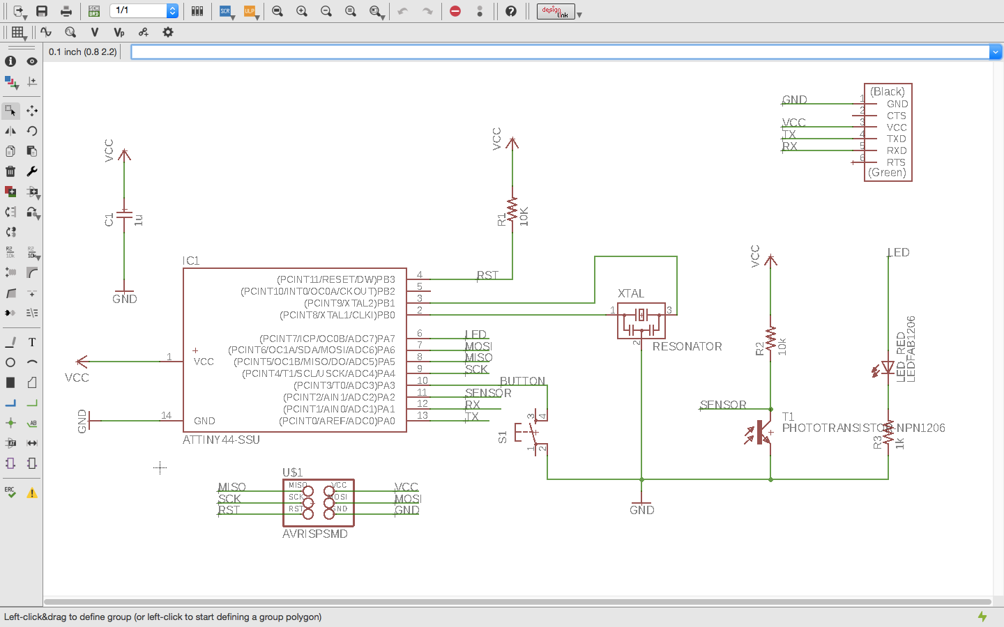 Schematics done
When my schematics was ready I clicked the “Switch to Board” button to create my board design.
Board Layout
Autorouter vs manually
This was more tricky. At first, I had a hard time understanding how I could figure out where to best place the components out. The where airwires everywhere. I first tried the Autorouter to help me find the best routes, but that just made everything more complicated. In all ways I placed the components, the Autorouter said it was only 70-92% good. I thought you had to get 100%, I then didn’t know you could start there, and then route the traces manually. But anyway, it was more fun to do it yourself. To route the traces I used the command Trace and connected the components. The wire turns red when the route is in place.
Lost connection
Early on I stumbled upon a challenge. For some reason, my board layout wasn’t connected to the schematic anymore. I couldn’t really find out why, but I noticed this when I could delete components and airwires without the software saying anything. I have read that in the free version of EAGLE, this can happen when you put a component below or to the left of the origin. Also if you close the board layout or the schematic and make edits to one of them, will break the connection.
Commands
For the board layout, I used some new commands and left some that I only used for the schematics.
- Route = route the traces
- Ripup = ripup a route
- Ratsnest = clean up the airwires
- Text = add text to the board
I also set some the Design Rules found in the main menu Tool/DRC, which stands for Design Rules Check. I did a few changes, mostly based on the size of the end mill that I was going to use, 0.4mm.
Clearance:
- Wire-wire: 0.4mm
- Wire-pad: 0.4mm
- Pad-pad: 0.4mm
- I made no changes to the Via since that is for when you have multiple layers on your board.
Distance:
- Copper/Dimension: 0.4mm
Sizes:
- Minimum width: 0.4mm
I didn’t use the File tab, which can be useful if one wants to save the design rules and store it with the board file.
Design
This was time-consuming. I don’t know why I started off so small and tight. It made it all very hard. At first, I didn’t know that I could route the trace under components. I also wanted my design to look good. I guess I spent almost 5 hours getting it to look good. I made one design where I had two routes under a component. It worked with the design rules, so it must have been ok, but since this is a fairly long process of designing, cutting, soldering and testing, so I decided to do some changes.
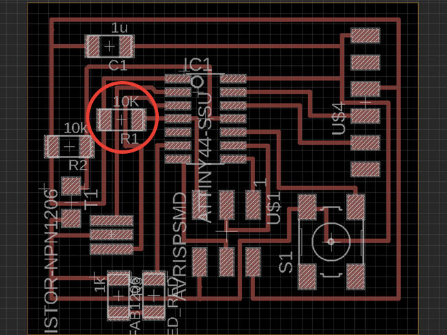 First design
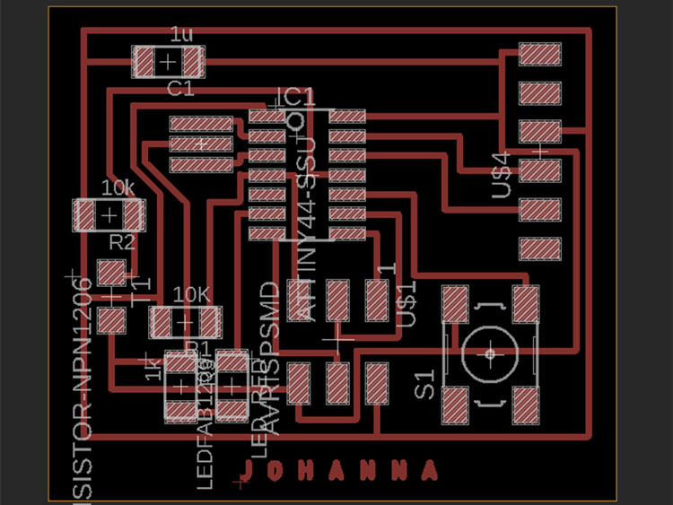 Second desgin
DRC showed an error saying “Airwire”. Apparently I had short airwires that were not connected to anything. I zoomed in to locate them and added some route to connect them.
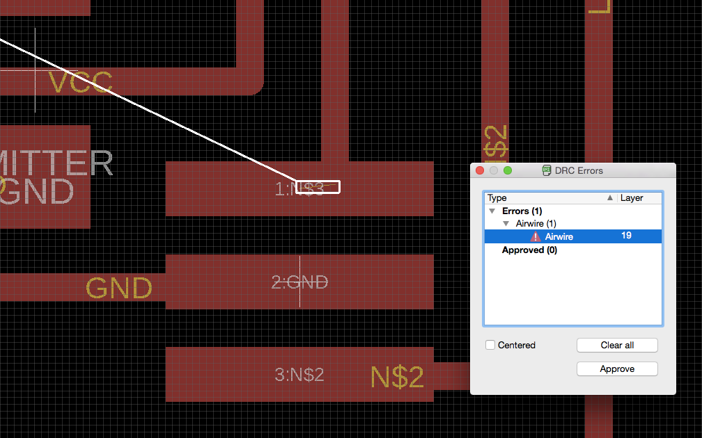 Error airwires
I added my name with the Text command. First I got a design rule message saying it wasn’t vector. In the settings for text, I changed the size and the thickness of the letters. This could have been done better looking, but it was all just for fun and not that important to get beautiful.
After that my board design was done! I thought.
Prepare for cutting
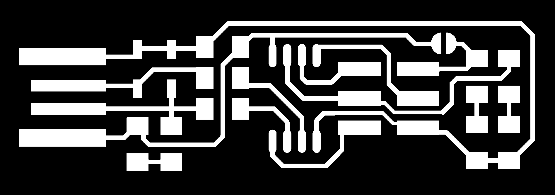
For the CNC mill, I need two pgn files, one for the traces and one for the cut. Exporting the board design to a pgn file was fairly simple, but I stumbled across some challenges. To create the png for traces, I selected only the layer that I have designed the board on, for me Top Layer. I then went to the menu bar File/Export/Image.
- File name
- Monochrome
- Resolution: 1000 dpi
- Area: Full
Text still showned in pgn file
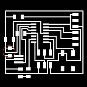
The pgn for the traces were created. For some reason that I don’t know, the name of two of the components was left in the png. It wasn’t there when looking at the top layer of the board design. For my first try, I decided to erase that in Photoshop. I later learned that you in Option/Set/Misc you can deselect “Display pad names” “Display signal names on pads” “Display signal names on traces”, however, that won’t take away the fact that the file still accounts for the text.
I have learned that it's good not to change the size of the png file since the chance to make it different than the cut-file is too big. However, since I was going to make a file to cut the board, I could just make sure it cuts away this extra part that I have got, to save material. This would have worked fine, however, in the end I didn't save any material. The origin of the pgn file was in the corner where I had the extra black area. That was where the machine started cutting. I could have solved this in two ways, either rotating the pgn 90 degrees before cutting, or change the origin of the end mill to start outside my copper plate.
Making the cut png became more complicated than I thought. I had learned to make a rectangle that was 1 mm bigger than the board. I would do this in layer 51 (a layer I didn’t use for this design). After exporting the pgn I could fill in the 1mm offset in Photoshop, but this didn’t work for me. I instead made two rectangles, on just as big as the board in layer 52 and one 1mm bigger in layer 51. I exported the file not as Monochrome but as Clipboard. I could then color the areas in Photoshop, what was going to be cut in black and the board in white.
I first noticed the mistake in the pgn cut file when actually cutting. This was when only doing one rectangle. I must have missed makeing the 1mm offset black in Photoshop because the cut only became one line on the bottom. When I changed this later on, the cut was then 1 mm higher up the the failed cut, which was a nice surprise (since I now had two rectangles).
 The pgn is had more black area than needed
 Monochrome picture in Photoshop
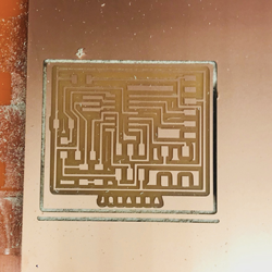 Result of first png cut file
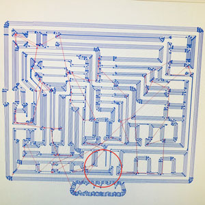
Traces in Mods
Cutting the board
I followed my steps from the prior week and it all when smooth. That's not entirely true. First time I did the calibration I could tell that my traces were too close to each other. Even though I had used the design rules, this happened. I had to go back to my board design and move the traces that were to close. I also changed my name that I had written on the board and made spaces between the letters to be able to read the name better.
After that it all went smooth. I made the traces and I cut off the board.
 Board cut and ready!
Components
My board was then cut and ready to make magic. I collected all the components from my component list and a few times I had to check with Emma that I had the right one “do we have different kinds of 6-pin headers?”
Then I had to fetch the right resistor for my LED. For that, I had to do some calculations to make sure I pick the a value that wouldn’t burn out my LED but still make it shine well enough. I had a look at the paper in the LED drawer which indicates what LED this was: 160-1167-1-ND. I wrote that in the web browser and added the text datasheet. I went to the site digikey and clicked on the datasheet. I used this site to calculate for the LED. In the datasheet for the LED I was looking for:
- Source voltage
- Diode forward voltage
- Diode forward current (mA)
I have learned that the Voltage in the USB is 5V. The Diode forward voltage I found in the datasheet. I picked 1.8 because that is the “Type” which means it’s the typical value. Sometimes it’s a min and max and then I would have picked the average. For Diode forward current the datasheet said 40mA.
- Source voltage: 5
- Diode forward voltage: 1.8
- Diode forward current (mA): 40
The wizard recommended a 1/4W or greater 82-ohm resistor. At Fab Lab we didn’t have any 100-ohm resistors, the smallest we had was 499, so I used that.
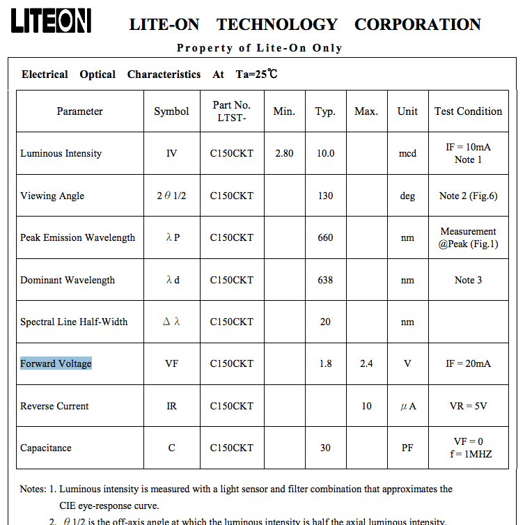 Forward voltage in datasheet
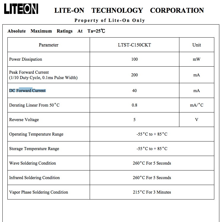 Forward current in datasheet
 Wizard recommendation
I placed all my components on my board to get an understanding of what to solder first. I started with the biggest component, the ATtiny.
Orientation
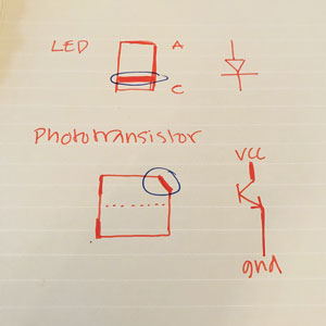
Soldering went fine, I actually got a compliment for them “nice and shiny” :). My biggest challenge was to make sure I put the LED and the Phototransistor in the right orientation. I learned that the cathode is marked on the LED and that the cathode always connects to ground (or indirect to the ground as in my case). The phototransistor has a cut off the corner. That corner marks the side that should be connected to VCC (or indirect as in my case).
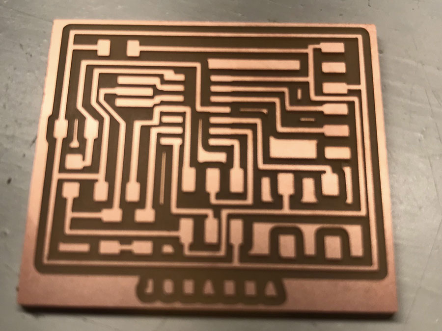
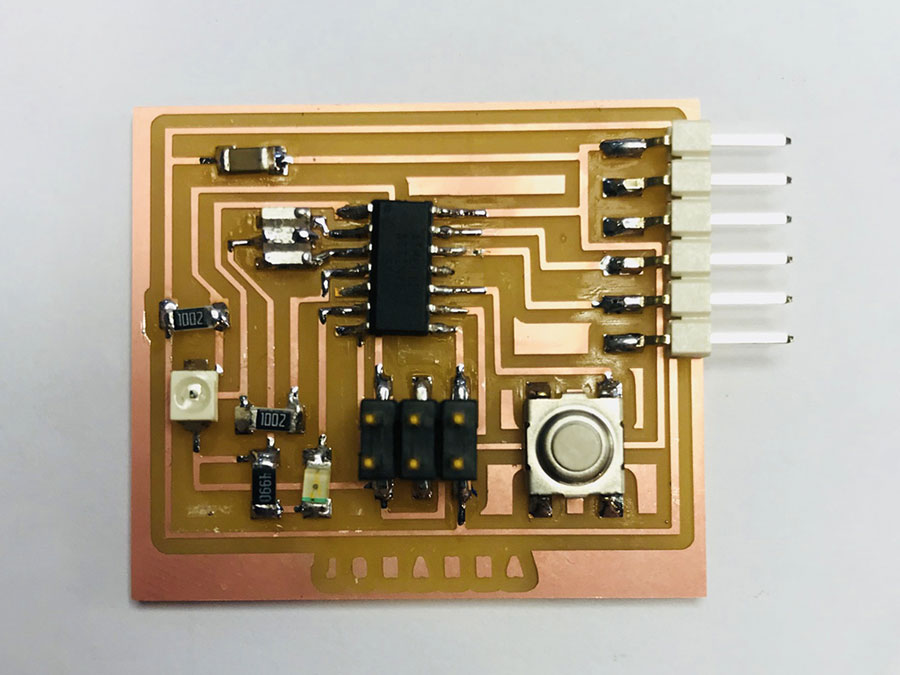 My Echo Hello board!
I checked that I had not shorts with a digital multimeter and after that my board was ready to be tested.
My programmer can see my board
Test the board
I connect my own ISP programmer to my Echo Hello board and then to the USB port on my computer. I used a flat cable to do so. When doing this it's important to check the orientation. I used Xavier’s picture from his weekly assignment week 4 and located the pins on my ISP programmer. For the Echo Hello board, I looked at my board design parallel to the schematic to figure out which pin was which.
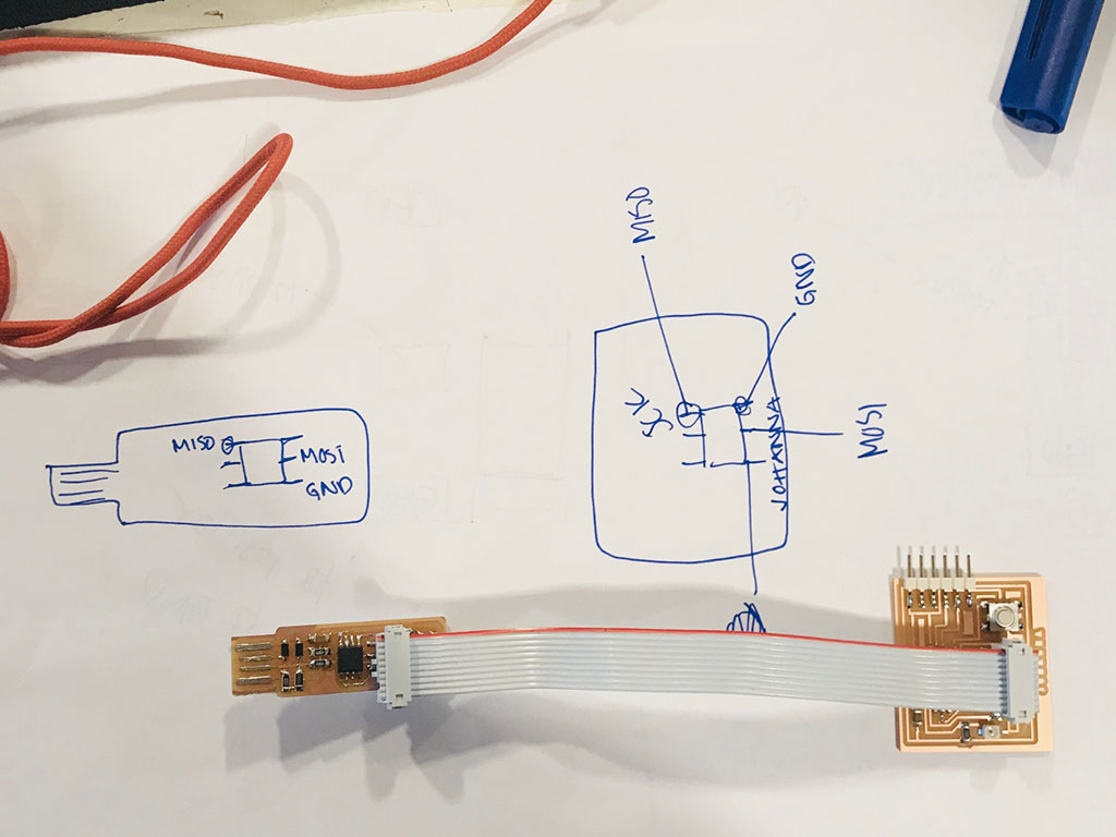 Connecting board to programmer in the right orientation
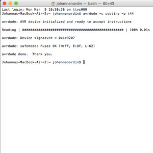
In Terminal I wrote the command “avrdude -c usbtiny -p t84” but I soon realized that I have a t44 in my Echo Hello and changed it to 44 instead of 84. My Echo Hello was working. I got the nice message in terminal. That means that my programmer can see my board and it’s ready to be programmed.
Download files here
Traces file
Cut file
Schematics
Board
group assignment:
assignment: use the test equipment in your lab to observe the operation of a microcontroller circuit board
Week 8: Computer-Controlled Machining
assignment: make something big
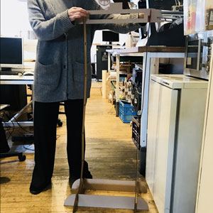
The weeks are just getting more and more fun! Such an amazing week! This week’s assignment was short and sweet “make something big”. I guess one of my biggest challenges was to come up with what I wanted to make. Before, I have been doing some stuff for my sister’s kids, but this time I wanted to make something that I can keep, and hopefully for long, reminding me of the time here in Amsterdam.
So I went to explore my everyday needs. One is that I don’t like putting worn clothes back in the wardrobe. I want to keep then a bit tidy and not just throw them on a chair. My dad has always, as far as I remember, have a “herrbetjänt”, a clothes valet, also called men's valet, on which his clothes were hung. I want one for myself.
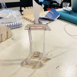
Simple prototype of the Herrbetjänt
Designing the herrbetjänt
Designing is not my best skill, not drawing on paper either, so I started off cutting out pieces in cardboard to get an idea of how the herrbetjänt could look. I wanted to make it stable and with clean cuts, with many different possibilities where to hang the clothes, bags or whatever I will want to hang there. Cardboard was a bit tricky to do so small, so I used thicker paper instead.
Fusion 360
When I had an idea of how I wanted my design to look I went into Fusion 360 to make my sketch. I feel comfortable with 2D modeling in Fusion 360 now, so it all went pretty smooth. I made the design parametric since I knew I would have to change the measurements later for the slots and a perfect press-fit. I wanted the press-fit to be stable, however, easy enough to take apart and move pieces if wanted.
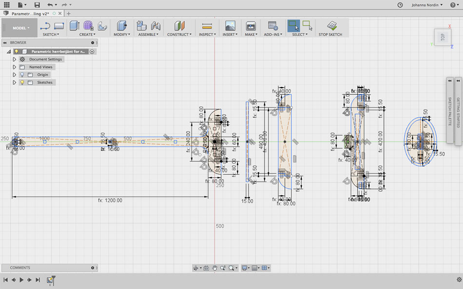 My sketch in Fusion 360
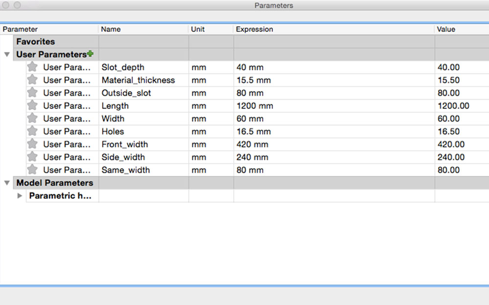 My parameters
Illustrator
From Fusion 360 I saved my sketch as a DXF-file and opened it in Illustrator. I cleaned up the design from construction lines and made the paths joint. This I had some troubles with. I thought I cleaned it up in Illustrator, but later in the machine software, it would show that I had some unjoint paths. I saved my file as a pdf for the machine software to read. My design was now ready to be milled!
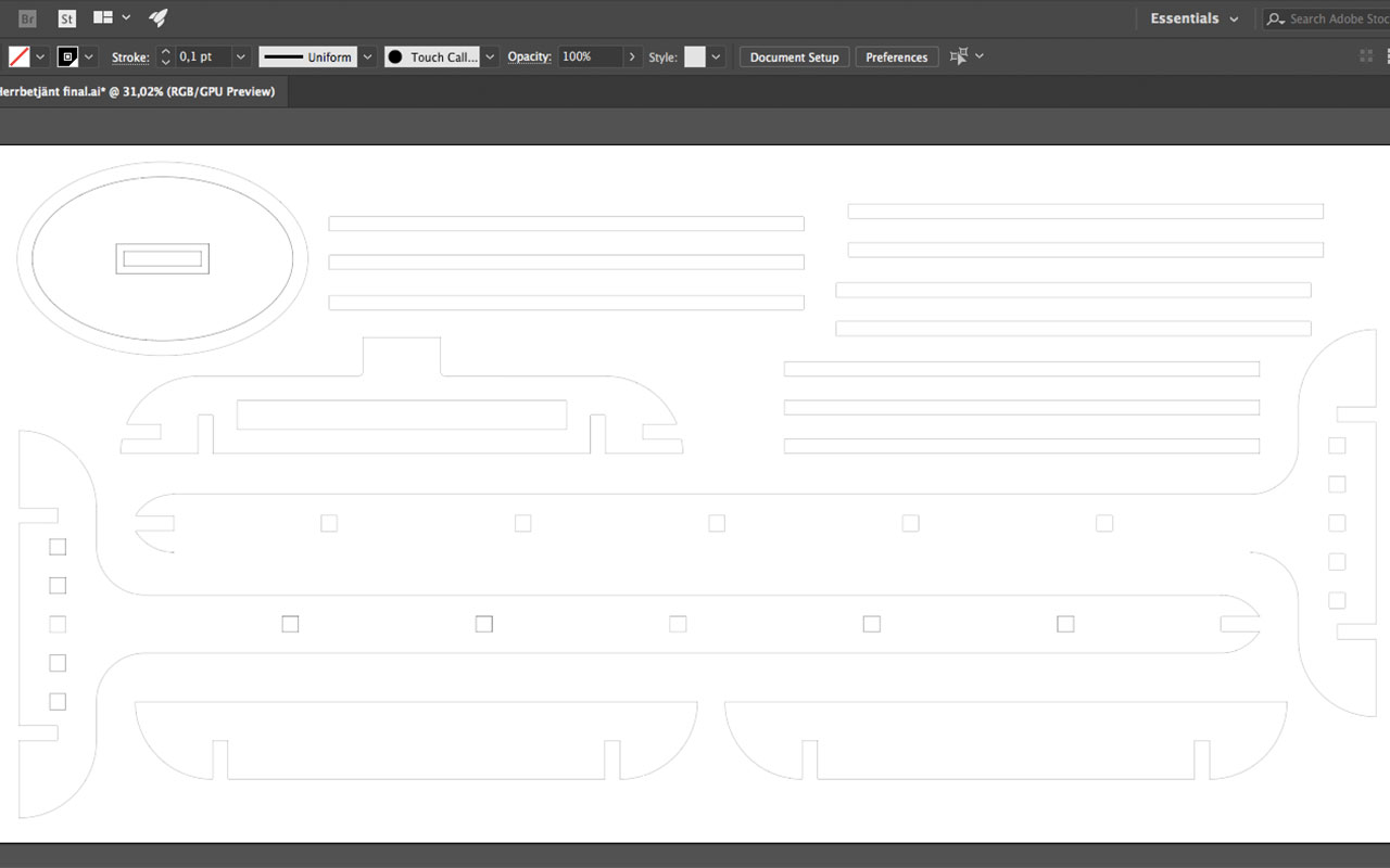 My desgin in Illustrator
My laser cut prototype in cardboard
Prototyping some more and testing the cut
But before I went to mill the whole thing, I first did a full size (almost, I had to scale it down to fit on the bed) prototype with the laser cutter. On purpose, I didn’t change the slot size, so I knew this prototype wouldn’t be stable, but I just wanted to get an idea of the design I had made; if I liked it, if it was too big or just straight ugly.
I also did a test of the slots and the holes, actually milling some test pieces to get an understanding of the machine. I made holes with different sizes, and slots with different widths. I was a bit quick when putting together the test design, so I forgot to make the opposite slots in the same size, to actually test the press-fit, now I had to test it on any piece, which is fine, however, would have been better to test the actual press-fit. I also could have made more test holes, and then try more measurements. To save material, I could have made the cut much smaller too. Moreover, I did get to test which of the t-bones or dog-bone I like the most.
 Dog-bone vs t-bones
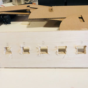 Hole test
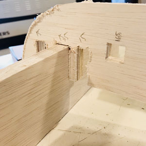 Slot test
I was now ready to mill!
Big CNC Machine
Shopbot and Shopbot Console
The machine we have at the Fab Lab is a Shopbot and it runs with the software Shopbot Console.
The process of making it ready for milling is:
- Turn the machine on, the big red switch on the side.
- Turn the software on, the Shopbot Console.
- Press K in the yellow field to be able to move the mill head. You don’t want it in your way when placing your material on the sacrificial layer.
- Place your material on the sacrificial layer.
- Measure it and make sure your design will fit.
- Screw it onto the board.
- Move the mill head closer to you to change the end mill. Loosen the mill head using two screwdrivers. Make sure your end mill is longer than the material you want to cut. Place the end mill so you have the material thickness plus some safe distance. Use the measurement tool.
- Set the X, Y, and Z for milling. X and Y are set by moving the end mill to your choice of origin. Then click the menu “Zero” and then “Axes X & Y”. It very important not to click the button which looks like it sets the XY-origin. Z is set by using the tool attached to the board. Test the connection by tapping it onto the end mill, a lamp should lit up in the software. Click the button with a Z on it. Hold the tool with two hands and watch when the end mill stops right above the tool.
- Do the settings in Partworks (a seperate process).
- Load file, “Part file load”.
- Make sure there is nothing else on the board.
- Turn on the ventilation.
- Make sure you know where the emergency brake is.
- Turn on the spindle, using the key on the side of the machine.
- Ready. Click start.
- Be ready to press space if something goes wrong.
 Place end mill in mill head
 Measure how long the end mill sticks out
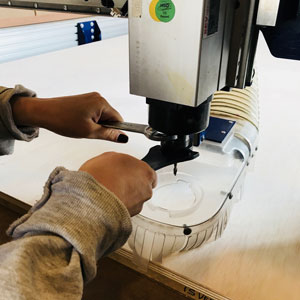 Tighten the mill head
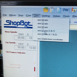 Click here to set X and Y
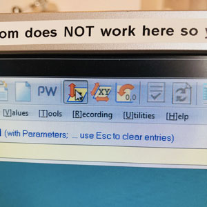 Click here to set Y
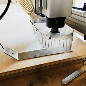 Z-tool
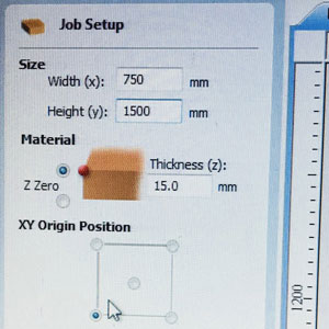
Job settings in PartWorks
PartWorks
To prepare the file for the Shopbot Console, we use the software PartWorks. In Partworks, I created a new file, and I set the dimensions for my design. I set width/height to 750mm/1500mm (my design was 711mm/1443mm and I wanted to be safe). This was the size in Illustrator, but since I wanted to cut in the direction of the grains, I later had to rotate my design, hence also change the dimensions to 1500mm/750mm. In this window, I also set the Material thickness to 15 mm.
I plugged in my USB with my pdf file and saved it in the computer. I Imported the file by using the “Import vectors” command. I had downloaded a plug-in for Fusion 360 to easily create dog-bones, but I found this being a bit messy, so I decided to do them in Partworks, which also gives you alternative to dog-bones. For the t-bones and dog-bones I used Fillet 2,5mm since I was using a 5 mm end mill. I placed the dog-bones on the holes and the t-bones on the slots, which I thought looked the best. I probably should have done a different version of t-bones on the slot; the ones that go further in, not to the sides, that would have looked better.
Make dogbones and T-bones in Partworks
Some of my vectors (paths) were still open. I used the command “Join open vectors” to make sure all were closed before milling.
The settings for which end mill is to be used is set in Tool Database:
- Tool type: End mill
- Diameter: 5mm
- Pass Depth: 3
- Stepover 2.5mm (50%)
- Spindle feed: 14 000 r.p.m
- Feed Rate: 20
- Plunge Rate: 20
- Tool Number: 1
I selected a fairly low speed, but a high spindle feed to make a nice and clean cut.
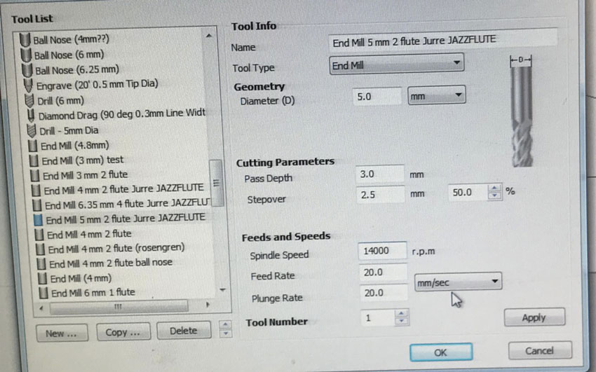 Tool setup in PartWorks
When all basic settings were done, I created the different toolpaths. I started with the pocket, then the inside and then the outside. This is for a similar reason for why you engrave first when laser cutting. The settings are similar with a few exceptions.
- Start depth: 0
- Cut depth 15.5mm for inside and outside (I decided to cut deeper than my material to make sure it would cut through) 7,5 mm for pocket
- I selected my saved end mill
- Machine vectors Outside/Right for outside, Inside/Left for inside
- Directions: Climb
- Add tabs to toolpath (I added 6mm thick tabs to the holes and 7,5mm thick tabs to the rest of the pieces)
I made sure the toolpaths were in the order of the milling, and then I saved the file.
Milling
First, everything when really smooth. The machine started with the pocket, just as planned, and it took ages. Nothing wrong though, I wanted speed 20 to not stress the machine.
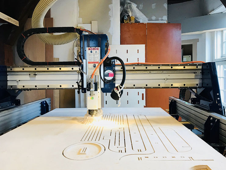 Ongoing milling
After about one hour of milling, Emma came running into the room. I stopped the machine, but without really knowing what had just happened. Me and David that was in the room, both with ear protection, didn’t react as fast as Emma. Emma had heard a sound that she didn’t like.
We turned off the spindle and had a look at the end mill. It was loose. Similar to what happened when Bas showed us the machine the day before. Then we thought that it was because of the friction that was created when doing the opposite direction as to climbing, but that wasn’t the case this time. We can only guess, but the mill head was probably not tightened enough. We changed the end mill since the used one now was a bit beaten. This meant I had to repeat the calibration of Z. X and Y were still set, which was important for me to continue my work.
This made the already long process even longer. I took a picture of the “Line”, that's the order of the milling, showing every “step” the machine takes. I was on line 38322.
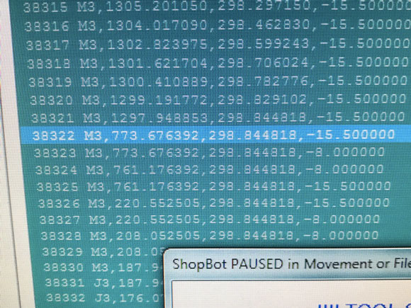 The milling stoppd on this line
Reading about starting the Shotbot from a line in the middle of a job tells you that one shouldn’t start on a minus line, ie when it is actually milling. So I had to find the last line that was at plus; a line before I stopped. To do so I opened the spf-file in a text editor. I searched for the line where I had stopped and went further up to find the first line that wasn’t on minus. That was line 33745.
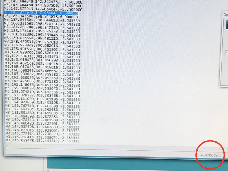 Start milling from this line
In Shotbot Console I went to the option “Start from Line”. I changed the heading of the pop-up window to “33745”. The software warned me and asked if I wanted to start from the line just before I stopped. But to be sure not to break the end mill by starting on a minus line, I changed the line to 33745. I clicked GO and held my fingers crossed. It worked!
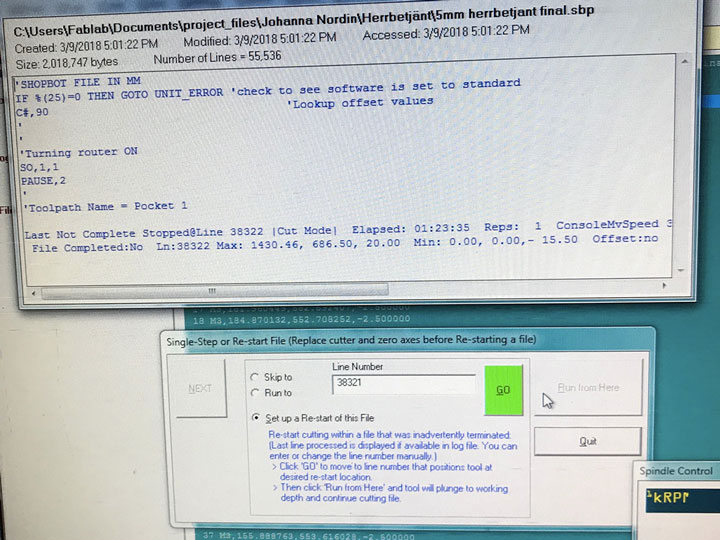 Warning message
I spent about two more hours with the machine, watching while it was milling, this time without ear protection. Everything worked fine.
Furbishing my herrbetjänt
When the milling was done I cleaned the machine and put away all the material that was left. I used a small saw to saw away the tabs in the slots and a rubber hammer and a wrote chisel to get the tabs from the holes. Plywood is made in layers, so sometimes the top layer came off. I noticed that if you hammer from the side you want to look the best, that will create the best results.
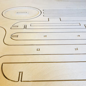 Milling done!
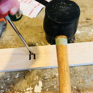 Rubber hammer and a wrote chisel
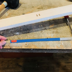 Little saw I used for the tabs
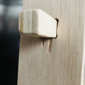
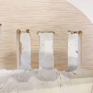
Some holes broke a bit
Then it was a lot of sandpapering to be done. The holes were really hard to make look good. The dog-bones and the tabs made the squares not look like squares anymore. And it’s a fine line of sandpapering too much and make the holes too big. In total I think I spent about three hours sandpapering the herrbetjänt, making it look its best.
Almost done! I might paint it later, but for now, I’m going to enjoy the nice looking plywood!
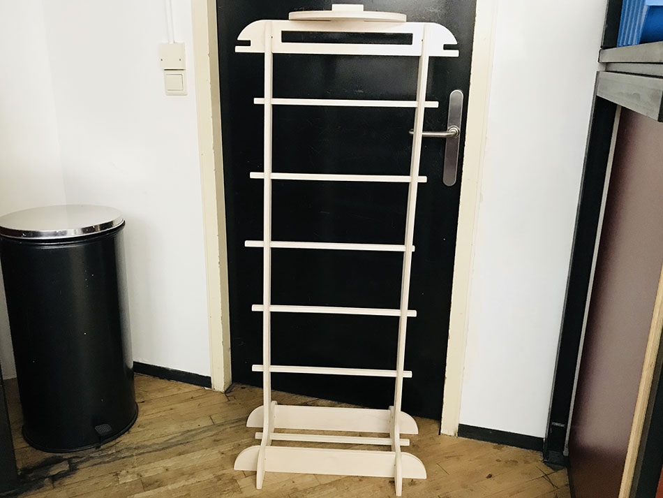 My herrbetjänt
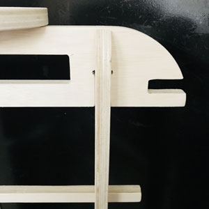 Extra hanger
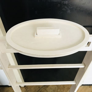 Bowl for jewelry and small things
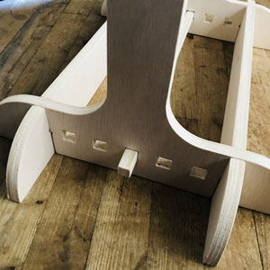 Place not used shelfs here
Download files here
Herrbetänt pdf
Herrbetjänt ai
Herrbetjänt dxf
Link to Herrbejänt in spb and crv format
group assignment:
assignment: test runout, alignment, speeds, feeds, and toolpaths for your machine
Week 9: Embedded Programming
assignment: read a microcontroller data sheet, program your board to do something, with as many different programming languages, and programming environments as possible
Getting started
What does “embedded programming” even mean? This is a tough week, not necessarily the weekly assignment in it self, but to really understand what I’m doing. I know parts of this week will be stuff that I just need to accept, thing that I might need more knowledge to understand. But I will try my hardest to understand most of it.
Install FTDI drivers
It started off exactly like that; me not understanding what I was doing or why. Before Thursday local session we were asked to “install FTDI drivers”. We got this link, and I just followed the tutorial to download the right version for Mac OS. But I will try to understand what I did. I know I have a FTDI header on my Echo Hello board. That is the one with six pins sticking out from the board, typically something that I would plug in somewhere. I googled but that didn’t really help, I got to a Wikipedia page which said something about it being a company specializing in USB technology. Something about converting RS-232 or TTL serial transmissions to USB signals. My conclusion is that the FTDI helps my computer understand what my board is saying.
But this installation was for later, it would take a while till I came to the point when I wanted my computer to talk to my board.
Test my board
This I had already done in a previous week. The process is to connect the board to the programmer using a flat cable, and to plug in the programmer in the USB port of the computer.
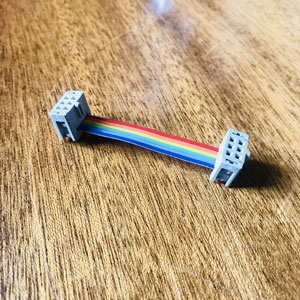
My own flat cable
I assembled my own flat cable, making sure the direction of the two pin sockets were the same. That makes it easier when connecting. I also made sure the board and the programmer were in line, with the same pin in the same orientation, ground to ground, etc.
In terminal I wrote the command that tells my programmer to look for a board called ATtiny44, “avrdude -c usbtiny -p t44”.
The programmer found it and I was ready to start programming.
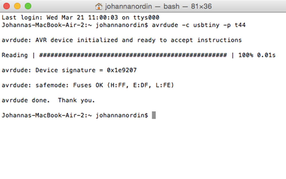 The programmer found my board
Arduino software setup
One way to program the board is by using Arduino software. I already had it installed on my computer. Arduino uses a very simple version of the programming language C. Some libraries are written in C++ thus it’s also C++.
The software is actually called Arduino IDE. IDE stands for Integrated Development Environment and it’s a software application and it normally consists of a source code editor.
Before starting to program, I had to tell the software what type of board I was going to program. In the menu bar of the Arduino software, under Preferences, there is a text field “Additional Board Managers URLs”. In that field I wrote “https://raw.githubusercontent.com/damellis/attiny/ide-1.6.x-boards-manager/package_damellis_attiny_index.json”; a link I have gotten from Emma that tells the Arduino software that I am using a thrid party board. I clicked OK and went to the “Tools” menu, “Board” and then “Board Manager”. I found the ATtiny, and clicked “Install”.
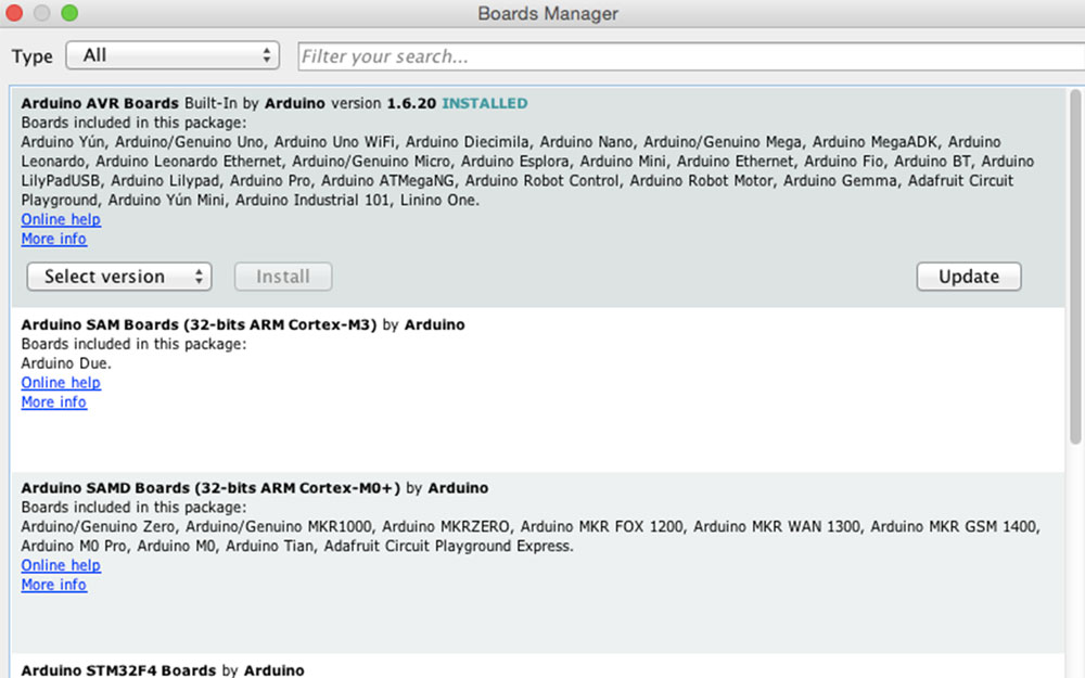 Board managers
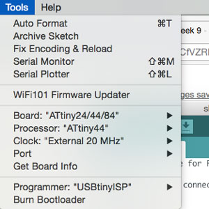
Settings for the ATtiny44
Then, under the menu “Tools” I could define the specific environment for my board.
- Board: ATtiny24/44/84
- Processor: ATtiny44
- Clock: External 20MHz
- Programmer: USBtinyISP
This is not enough for the setting to start working. For that I need to run the command “Burn Bootloader” to “empty” the board from prior information and apply the new settings.
Programming
The weekly assignment this week is to “program your board to do something”. Since I have a few different components on my board, I have a great variety of things I can make it do. I decided I wanted to code at least two different things, and if I got time left I would code something more. First start easy and make the LED blink when pushing the button. Then as a second thing, I wanted to make the board tell the computer, through the Serial Monitor (the connection between the board and the computer from where one can send and receive messages), that when the phototransistor is at a certain level, being dark around it, a text message should say “Good night”, and when lit up level, it should say “Good day”.
Arduino software
The code in the Arduino software is called sketches. All sketches have two void type functions; “void setup” and “void loop”. The setup is only run once by the microcontroller while the loop continuously run over and over again.
1) LED lit up when pushing the button
So to make my LED blink when pushing the button, I used the control structure “if...else”. A great library with all references to Arduino’s structure, values, and functions can be found here, this I used a lot during programming.
Before starting, I needed to get an understanding of the different pins, and which one is connected to the led and the button. I had learned that the pins on the ATtiny does not exactly translate to the pins in Arduino IDE since that one relates to a microcontroller called ATmega. So I used Emma’s scheme to understand which pin was which.
The LED is connected to the pin PA7 and the button to pin PA3. These have to be defines in the code. The code “int” converts a value to the int data type. So in the code, before void setup, these can be defined.
int LED = 7;
int BUTTON = 3;
In the void setup, I tell the micro controller the different “pin modes”, ie. the use of the pins (actually it’s changes the electrical behavior of the pin); INPUT, OUTPUT or INPUT_PULLUP. The INPUT_PULLUP enables the internal pull-up resistor in the microcontroller which acts like a large current-limiting resistor.
void setup() {

pinMode(LED, OUTPUT);
pinMode(BUTTON, INPUT_PULLUP);
}
So for the loop I need to write the code that tells the LED to lit up when pushing the button, ie I want to read the voltage in the button pin when it’s pushed and when it’s not. To do that I need to create a new variable that will save the data.
For this I create another int, I give it the value 0.
int LED = 7;
int BUTTON = 3;

int BUTTON_value = 0;
For the loop, I need to define what happens when pressing the button. I first tell the microcontroller to read the value of the button. I do this with digital read, which reads the value from a specified digital pin, and could either be HIGH or LOW.
void loop() {
BUTTON_value = digitalRead(BUTTON);
I then do my if...else command. “==” means “equal to”.
void loop() {
BUTTON_value = digitalRead(BUTTON); // read the value of the button
if (BUTTON_value == HIGH) { //when the button is not pressed
digitalWrite(LED, LOW);//the LED is off
}

else {
digitalWrite(LED, HIGH);//the LED is on
}
}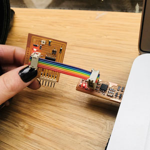
The LED lid up when pushing the button
It worked, my LED lit up every time I pressed the button.
During my first try, the LED was lit up when not pressing the button and turned off when pressed. I then figured out that the LED pin has 5V when the button is not pressed, meaning it is HIGH. So when button pin is HIGH, LED pin should be LOW.
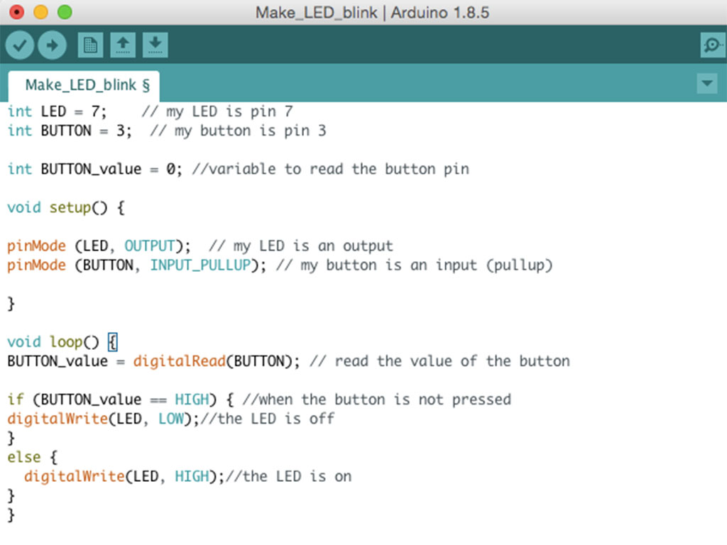 My code for the LED to lit up
2) Good Night/Good day message on serial monitor
For this to work, I need to include the library SoftwareSerial.h to be able to send the information I’m getting from the micro controller to the computer.
#include SoftwareSerial.h> //added a library to use the Serial MonitorI then have to define the pins I’m using for my serial communication.
On the FTDI:
- Pin tx = Transmitting (the pin the computer use to transmit)
- Pin rx = Receiving (the pin the computer use to receiving)
Pin rx is pin number 1 in the schematic, but I will define it as pin number 0 in my code. This is because FTDI has the priority. And the same goes for pin tx that has the number 0 in the schematics, but will be pin number 1 in the code.
I could have use the code “#define” but since “define” can mess up the code if the word is used in any other place, I will use “int” instead.
int rxPin = 0; //the receiving pin
int txPin = 1; //the transmitting pin
SoftwareSerial Serial(rxPin, txPin); // to set up the serial object
The phototransistor that reacts to light is connected to pin 2, which is an analog input pin. I also need to create a value for the phototransistor to read.
int pin_phototransistor = 2; //the phototransistor is connected to pin 2
int value_phototransistor = 0; //value for the phototransistor to read
Now when all values are set, I can go ahead and write the code for the setup that will run once. I set the pins; the rx to input, the tx to output and the phototransistor to input as well. I also need to tell the SoftwareSerial to enable communication. I set the number to 9600 since that corresponds to what I will set in the serial monitor.
void setup() {
pinMode(rxPin, INPUT); //the rx pin is the input of the communication
pinMode(txPin, OUTPUT); //the tx pin is the output of the communication
pinMode(pin_phototransistor, INPUT); //the phototransistor is an input
Serial.begin(9600); // to enable communication, should correspond to serial monitor
}
In the loop I tell the microcontroller to read the value of the phototransistor. The value can be more than HIGH or LOW, (0V or 5V), like in the case with the LED. For the phototransistor, the voltage can be anything between 0-5V, so to read this analog sensor, I need to read analog voltage.
To read the voltage from the analog pin, you can use the formula: V=(data)*(VCC/2^10)-1 in this case V=(data)*(VCC/1024), 1024 because the microcontroller’s ADC (Analog Digital Converter) has a resolution of 10 bit. This I can read in the datasheet of the ATtiny44.
Since part of this week's assignment is to read a datasheet, I will also, shortly add some things one can read about in the datasheet. To start with, the datasheet is very long, 286 pages !!!) and before you get familiar with it, it's very hard to grasp and get an overview. It has 27 bookmarks which makes it easier to navigate. The pin figuration is very useful and something I have gone back to many times. It tells the characteristics of all the pins. In the datasheet, there is a section about clocks. I have used the settings for using an external clock, which one can read more about in section 6.2.1 External Clock. In section 7, Power Management and Sleep Modes, there are explanations about how to put the microcontroller in sleep mode to save power. In section 20, Electrical Characteristics it says that the maximum operating voltage is at 6V. Stresses beyond those listed under “Absolute Maximum Ratings” may cause permanent damage to the device. I run my microcontroller on 5V from the computer's USB.
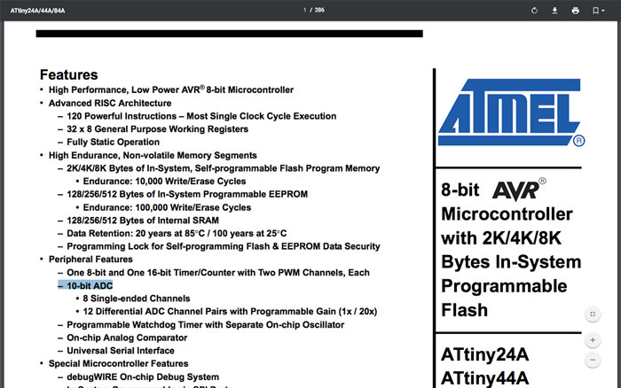 Datasheet of the ATtiny44
After that I add my if..else command. I picked the value 400. If the value is bigger than 400 the serial monitor will type “Good night”, if not it will say “Good Morning”.
void loop(){
value_phototransistor = analogRead(pin_phototransistor); // read the value of the phototransistor
if (value_phototransistor > 400) { //if it's dark
Serial.println("Good night");
}
else {
Serial.println("Good morning"); //is it's light
}
}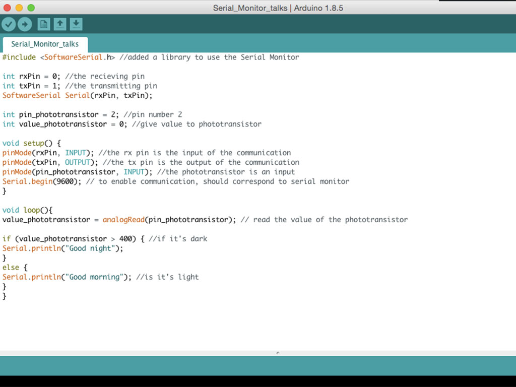 Code for the serial monitor to talk
To be able to see my message, I need to connect my board with the FTDI cable. I made sure the GND pin was connected to the GND on the cable, the black one. I selected the port in the top menu and then I clicked Serial Monitor to see my data.
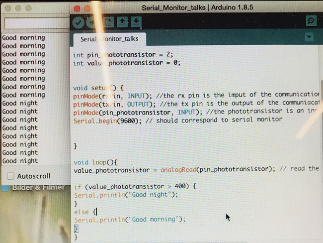 Good morning, Good night
Download files here
Make LED lit up when pushing button
Good morning / Good night
group assignment:
assignment: compare the performance and development workflows for other architectures
Week 10: Molding and Casting
assignment: design a 3D mold around the stock and tooling that you'll be using, machine it, and use it to cast parts
There are so many steps in this assignment, and thinking negative and positive parts really messed up my head. Also, just the difference between molding and casting is confusing. Google explains: “Molding is the process of manufacturing by shaping liquid or pliable raw materials using a mold or matrix, which have been made using a pattern or model of final object. But, Casting is a manufacturing process in which a molten metal is injected or poured into a mold to form an object of the desired shape.” This didn’t really make me smarter, but I guess it means that I first need to do a mold, then pour something in it, ie. casting my final design. But we are doing this is three steps, first using a CNC mill to create a positive mold out of wax. After that, I’m creating a negative mold by casting, i.e pouring material into the wax mold. After that I’m pouring another material into the negative part, making a positive part; my final object.
The hardest part is to decide what to make. I have a ring that I really like, a ring that some of my friends have said they would like too. I wanted to do some changes to it, to make it a bit more “mine”. I thought about engraving it, but that was too tiny and wouldn’t probably work, so instead, I designed a ring that looks more or less exactly like the one I already have.
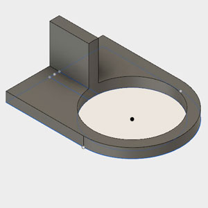
One part of the ring in Fusion 360
Designing - Fusion 360
I designed the ring in Fusion 360, now a bit more comfortable with 3D modeling than before, but still hard though. To make the actual ring wasn’t that hard, more or less some rectangles and some circles. I made it two-part, dividing the ring where I thought it was most appropriate.
What was hard was to build the box around the parts that would keep the liquid material in place when curing. To be able to pour the material down the mold I also needed a conduit connected to the ring. Apparently, a lot of bubbles are created when casting, so I also needed to create paths where the bubbles could escape; air vents. To not stress the end mill when cutting 90 degrees angles, I sloped the walls of the box. I also added holes on the bottom of one part and pins sticking up on the other, so-called “registration marks”. Those would connect the two pieces and make the mold more stable and in place when pouring the material. I saved the two pieces as two STL files by right-clicking the body in Fusion 360 and selecting “Save As STF”.
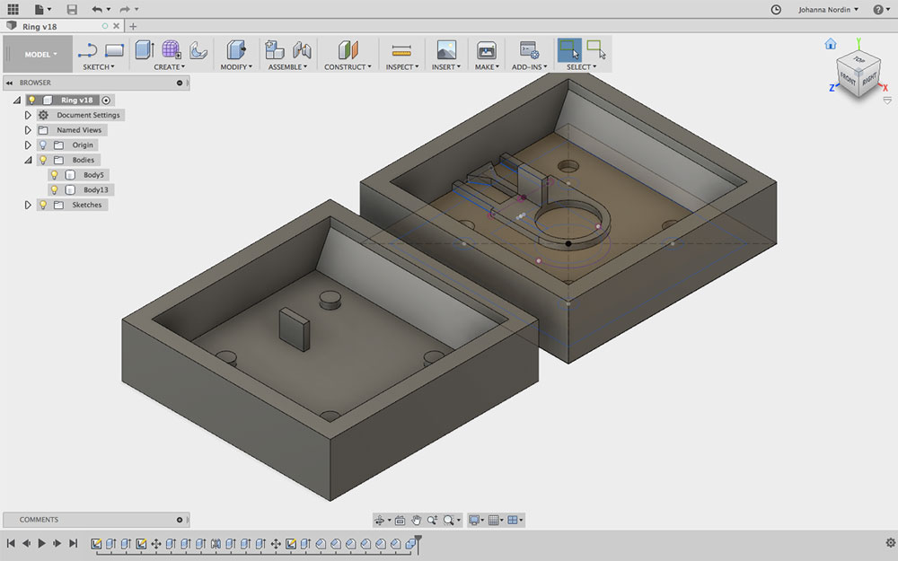 My design in Fusion 360
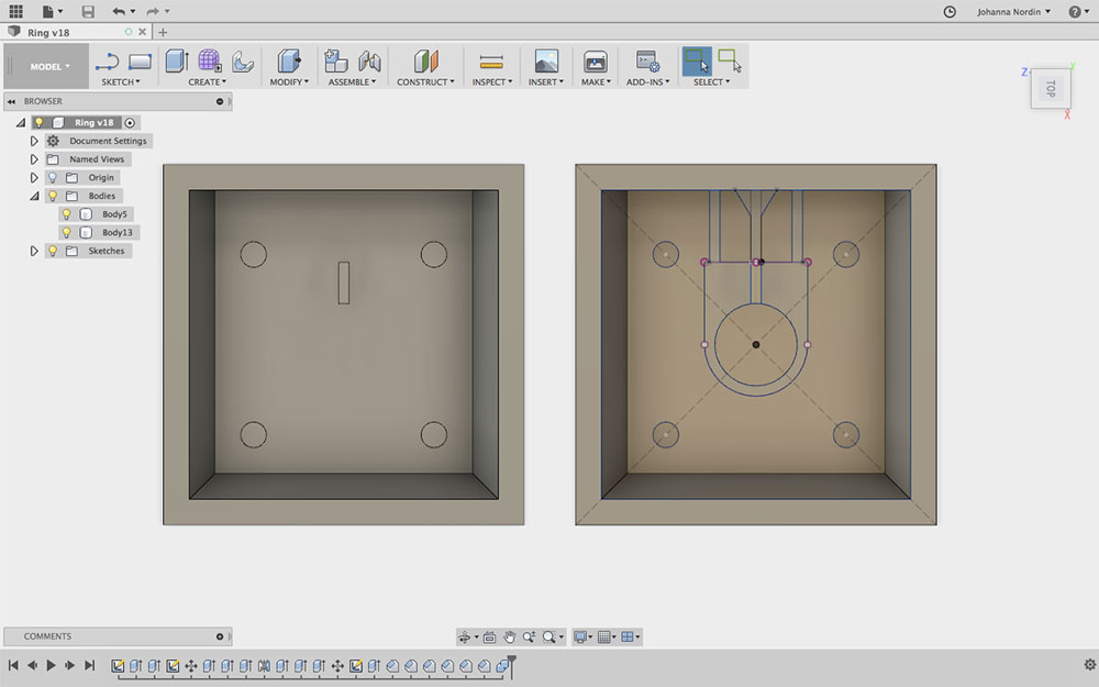 My design in Fusion 360
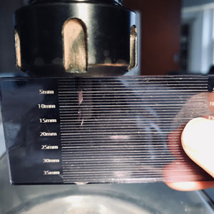
Measure the part of the end mill that is out
Milling
Prepare the ShopBot
This process was similar to the week of making something big, but this time we were to mill in wax. I attached the wax block to the sacrificial layer on the Shotbot. I used some blocks of wood and double-sided tape to attach the wax and make it stable when milling.
I was going to use a 3 mm flat end mill with 2 flutes, that was a good choice for milling in wax I was told. I attached my end mill to the mill head and made sure it was tightened. I measured the part of the end mill that was out and made sure it was more than I was going to mill.
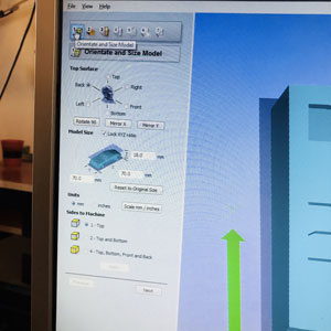
Orient and Size Model
ShopBot PartWorks3D
Opening up PartWorks3D, the first thing I did was to upload the first stl-file, I picked the file with the majority of the parts of the ring. PartWorks3D is more straightforward than PartWorks when not 3D-milling; it has 7 different steps to follow.
The first step is “Orient and Size Model”. I could rotate the surface, I picked “Back” because that worked best for my design. I made sure the size of my design was correct and I picked “mm” for units to be sure. I clicked “Apply” and then next.
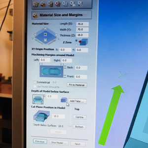
Set Model and Material Size
Next step is “Set Model and Material Size". My design was 70x70x18 mm. I picked the “Z Zero” to top left corner. I also unclicked “Use Model Silhouette” since I was not going to cut any parts away, they were going to stay in the wax. Same for tabs, I didn’t add any for this reason. For “Depth Below Surface” I wrote 18 since my design had the depth of 18 mm.
Step three is “Roughing Toolpath”. In this step, I decided the settings for my tool. I was going to use an end mill of 3mm.
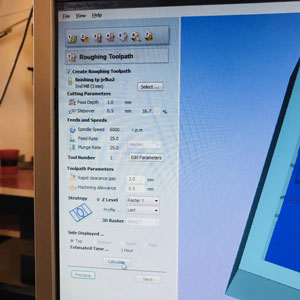
Roughing Toolpath
Cutting Parameters
- Pass Depth: 1.0 mml
- Stepover: 0.5mm (16.7%)
Feeds and Speeds
- Spindle Speed: 6000 r.p.m
- Feed Rate: 25 mm/sec
- Plunge Rate: 25 mm/sec
I then clicked “Apply”.
Toolpath Parameters
- Rapid clearance gap: 2.0mm
- Machining Allowance 0.5 mm
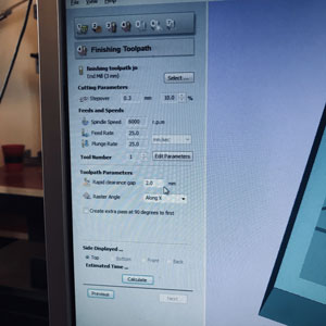
Finishing Toolpath
In “Strategy” I set the “Z Level” to “Raster Y”, which is the direction this toolpath will take. After that I clicked “Calculate” to get the time. It was going to take 1 hour.
In step four, “Finishing Toolpath” the settings where similar as for the roughing toolpath. I was going to use the same end mill that I used for the roughing toolpath, but with slightly different settings; I would change the stepover to 10% and change the “Raster Angle” to “Along X”. After that, I clicked “Calculate” to get the time; 19 minutes.
The fifth step is for cutting which I wasn’t going to do.
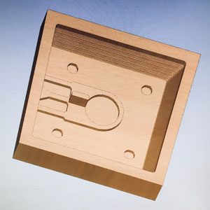
Preview of the toolpaths
The sixth step is “Preview Machining”. I checked my two toolpaths and both looked fine.
In the last step, “Save Toolpaths”, I saved the toolpaths as two different files and I also saved the settings for PartWorks3D.
I then did the same process for the other part of the ring, the other DXF file.
ShopBot - milling
I turned the ShopBot on and opened the ShopBot software. To set X, Y, I moved the mill head to my origin using the arrows on the computer. In the menu, I clicked “Zero” and then “zero axis (X & Y)". To set Z I used the tool on the machine, made sure it was connected, and then clicked the button “Z”. I uploaded my file and was now ready to start milling.
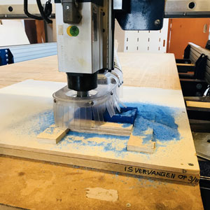
Milling my mold
After about an hour my roughing toolpath was done and I uploaded the file for the finishing toolpath. 19 minutes later, my first piece was done. I changed the Y for the next cut, my second piece. Since the wax block was 150 mm long, my design 70x70mm, I changed X to +75mm to start in the right spot. Then the whole process of milling again. About 1 hour and twenty minutes later my mold was done! I cleaned the machine, saved the “cut dust” to be melted and used again, and brushed my mold clean.
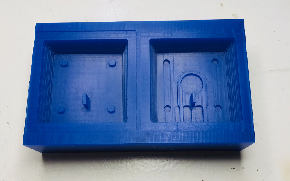 Milled and clean
Creating the negative
This process is done in the ventilation cabinet since the fumes can be toxic. I also used gloves and protected myself with comprehensive clothing to be safe.
For some reason, I decided to use Vytaflex 50 for my negative. It's a “Urethane Rubber Compound” and it’s mix ratio for part A and B is 1:1 in volume. I used cups and filled them up the same height to then blend the two parts together. I poured it into my model and then I waited. I left it there for more than 24 hours (the curing time was set to 16-24 hours), but it never cured. For some reason, it stayed sticky and too soft. I decided to take the Vytaflex out and clean up my mold and go for another material.
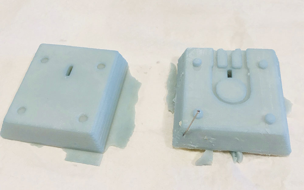 My cast using Vytaflex did not cure
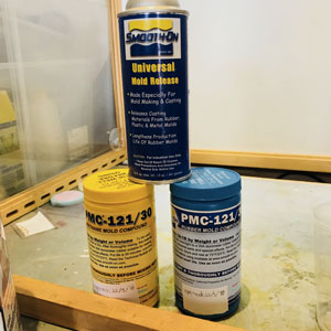
PMC 121/30 wet and Mold Release
For my next try, I used PMC 121/30 WET, a soft and flexible liquid rubber. I mixed it by 1:1 ratio, part A, and part B. Before pouring it into the mold I sprayed the mold with “Mold Release”, which will make it easier when taking the cast out of the mold.
Easter came and I had to wait a few days to check on my cast. This time all went great! The cast was steady and good. It was a bit sticky on the surface, but that was from the release. I sprayed it with release again to prepare it for the final casting.
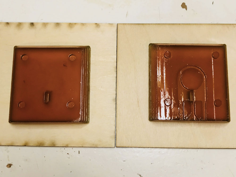 My two molds ready for final cast
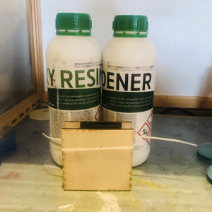
Epoxy
Creating the positive, final cast
For the final cast, I was going to use epoxy. At the Fab Lab, we had a SUPER SAP® CLR Epoxy System which is a clear liquid epoxy resin. With that, I can use different hardeners, but we only had the Super Sap® CLF (FAST) Hardener so I used that. It was hard to get the mix ratio right since I was only going to use a small amount of liquid and I didn’t find any small cups or measuring bowls. The mix ratio is 2:1 meaning two parts of the epoxy and one part of the hardener. I stirred it slowly but for a long time to make sure the two were blended.
For my mold, I had tightened the two parts together using some plywood and some tie wrap to secure it. To pour the epoxy into the mold was really hard. It was hard to not make more bubbles, make sure I poured enough but not too much, and to get it everywhere in all the angles.
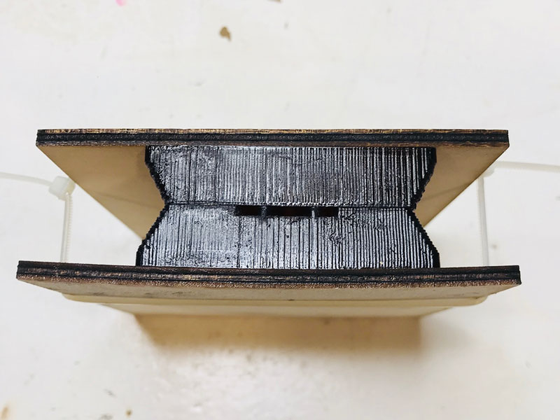 Tightened the two parts together
I left my cast in the mold overnight. The next day I took it out, and as I thought the bubbles in the epoxy made my design a bit deformed. I have learned that the chance of getting bubbles in your cast when the design has 90 degrees angles is more or less unavoidable. However, it still looked a bit cool. One bubble was just in the middle of the cross, which actually looks like I designed it that way.
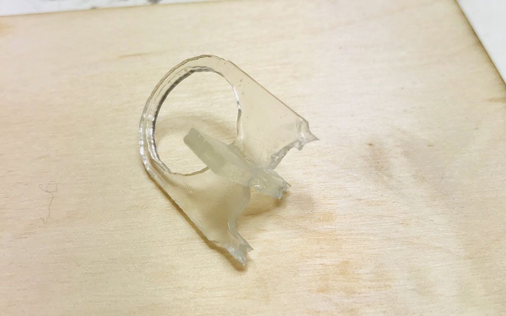 This is how it looked when I took it out from the mold
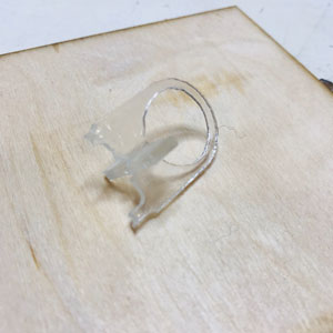
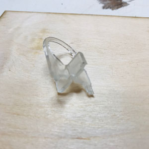
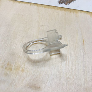
You can tell on the ring the rough edges from the wax mold, that the CNC mill couldn't cut a smooth circle.
What I'm really happy about is that you can tell that the mold parts were really tight together when pouring in the epoxy. There is no trace of material wanting to pour out from the mold except from the air vents which is almost unavoidable in this case when I didn't measure the amount of material and compared it to the volume of the object.
All in all, I'm happy with the learnings I have gotten and will make another cast with another material to try my luck again. Maybe a flexible material this time.
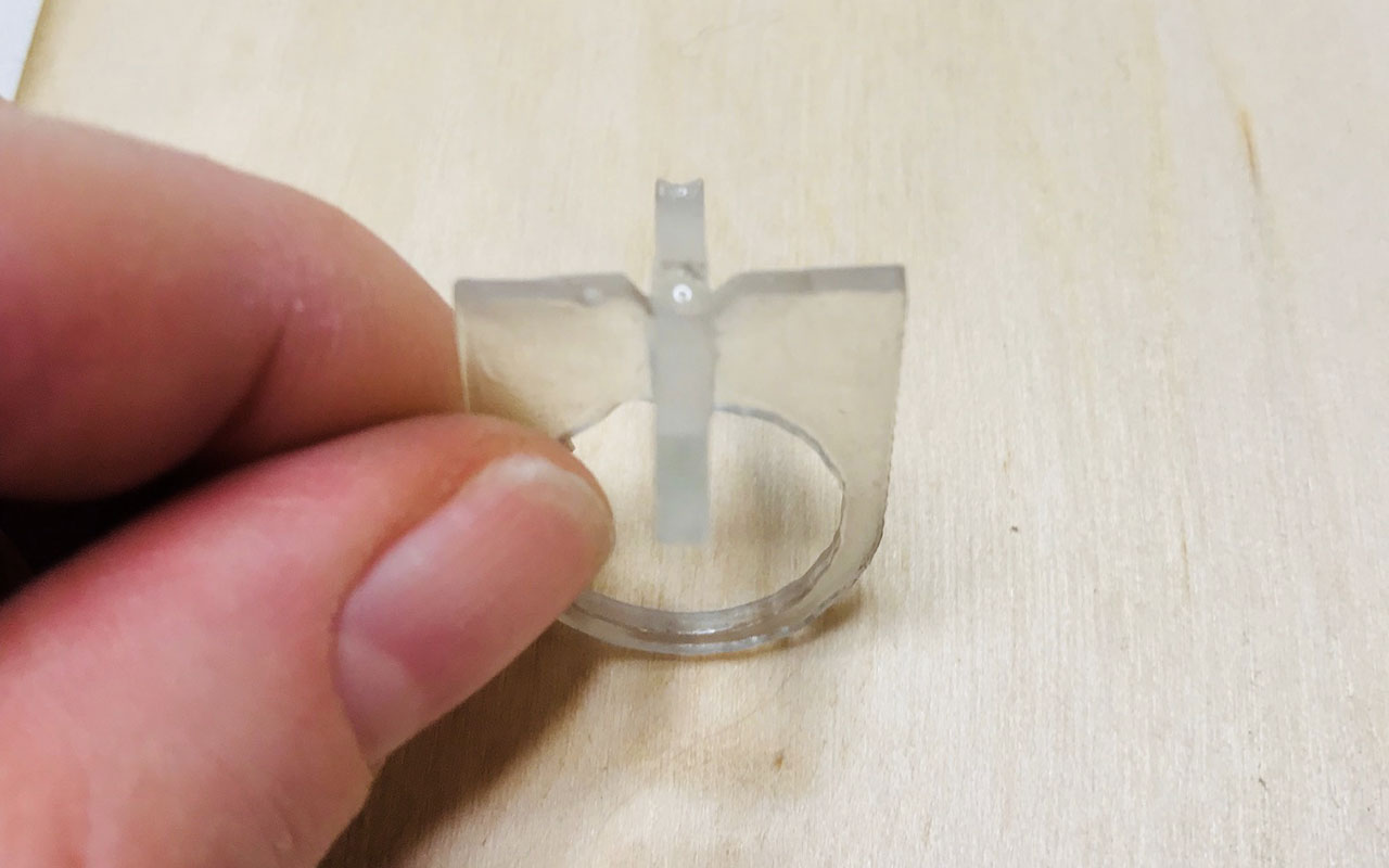 My ring
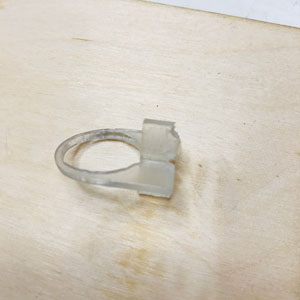
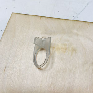
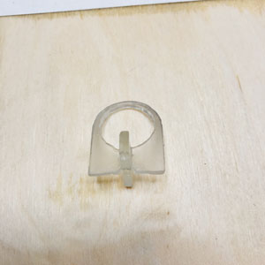
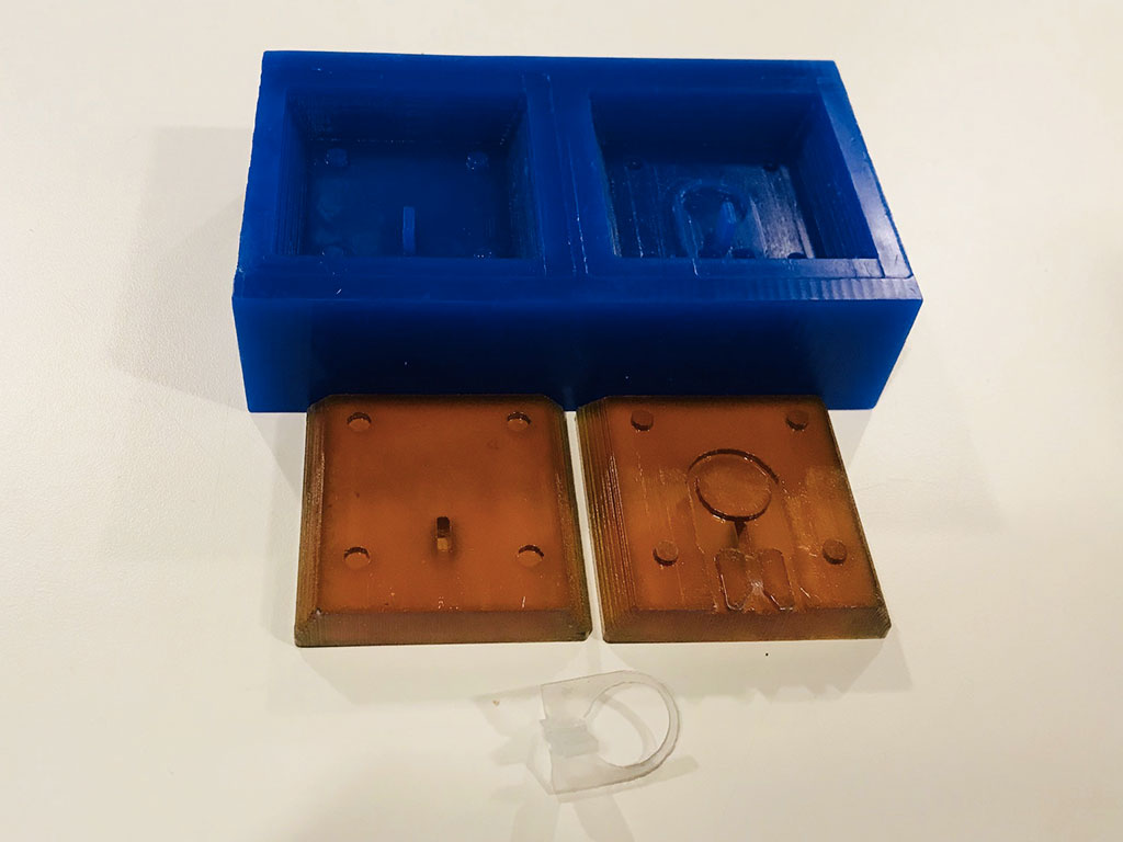 The positive mold, the negative mold, the object
Download files here
First part of the ring STL
Second part of the ring STL
Design of ring f3d
group assignment:
assignment: review the safety data sheets for each of your molding and casting materials, then make and compare test casts with each of them
Week 11: Input Devices
assignment: measure something; add a sensor to a microcontroller board that you have designed and read it
Interesting week! I guess you can make it as easy or hard as you please. That is a struggle of mine, continuously thinking I making things that are not challenging enough. But they are - at least for me. But the feeling of not making “cool” stuff is hard to get rid of.
Reed switch
We have already done a few things with input devices; we added a phototransistor and a button to our Echo Hello board, which is more or less what this week is all about. Since the final project is geting closer, I thought I should use this week to learn about an input device that I might use for my final project. That would be a so-called reed switch. When the reed switch is exposed to a magnetic field, the two materials, the reeds, inside the switch pull together and the switch closes. When the magnetic field is removed, the reeds separate and the switch opens.
The Fab Lab ordered this reed switch, there are many, but many are very big even in SMD-format. We ordered this one that was 17.6mm long.
Eagle
I decided to make a new board, similar to the Echo Hello but only with the components I needed to test the reed switch.
Create new icon
In Eagle I soon noticed, when adding the different components to my schematic, that I didn’t have an icon for the reed switch. This became one of my biggest challenges this week, to make the icon. But even before that, I didn’t even know that it was possible; to make your own icons for the board design. It is cool to realize how many things I learn here, big and small.
I watched this tutorial to learn how to make your own icon. However, in this tutorial, the guy is showing how to make a component with many pins that more or less look the same in the schematic and the board design. But my reed switch looked nothing like that. I actually couldn’t find the design of how the schematic icon should look, but I figured it was less important than getting the board icon right. I googled reed switched and made a schematic icon that was similar to those. Now when googling this again, I found many. I then thought that it was a specific one to the specific reed switch I was using, which is not the case.
Schematic
I had no challenges in this step except making the schematic icon for the reed switch. I used the same commands as during the week of Electronics Design to place, name, label and connect the different components.
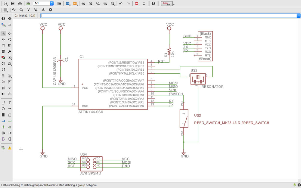 The schematic for the input device board
This is the list of components I added:
- 6-pin header
- Microcontroller ATtiny44A
- FTDI header
- 20 MHz resonator
- Resistor (10k)
- Reed switch
- Capacitor (1uF)
- Ground
- VCC
I decided to use a 20 MHz resonator and use it as the external clock. I only needed one resistor for the reset pin, for the reed switch I was going to use the pull-up resistor and activate it in my code. The ATtiny44 needs a capacitor between VCC and GND, preferably close to the microcontroller. Other than that, just the regular components; the 6-pin header to connect to the programmer and the FTDI header to be able to use the serial monitor.
Board design and Photoshop
This is always a bit tricky, mostly because I for some reason want to keep the board small and good looking. Like last time, I spend a good amount of time moving the components around to make the traces. When I was almost done, I figured it was a really boring board. My quick fix was to make the board look like a cat.
To not just make the traces look like a cat, I changed the dimensions of the board and made the whole board cat-shaped. This is way easier than I thought. Just like making a line or a rectangular, you can delete and add a line to your dimension.
I had some challenges when exporting the two files; the trace file and the cut file. The trace file went ok. I had to pick the top layer and the pad layer to get the right design, the pads I made for the reed switch were at that layer. I also had to erase the component itself in Photoshop after exporting the file since I don’t necessarily want the mill to cut the shape of the component, only the pads are needed.
The cut file, however. Last time when designing a board I made two different rectangles. This time a had a shape of a cat. I learned that when doing this way, I make a rectangular in another layer as last time, but I only export the dimension layer. This will result in a png that is black and has a white line in the shape of the cat. What I first forgot was to fix this file in Photoshop which messed up my cut (tell more about that later). I had to make sure the share of the cat was white and the surrunding black.
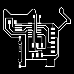
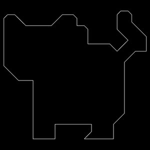

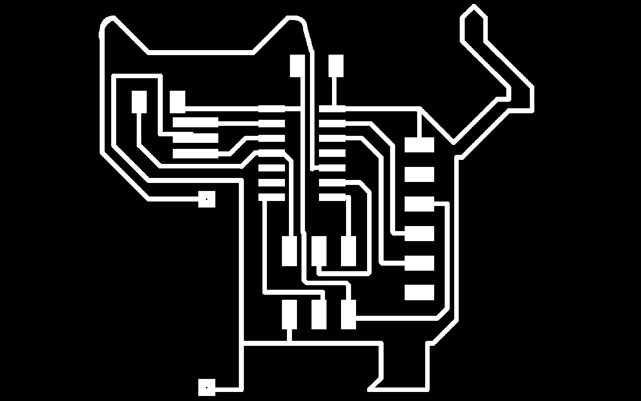 The traces ready for milling
Milling
As I mentioned, I had made my cut file the wrong way which messed up my board. Actually twice. The first time I didn’t even notice because the cut didn’t go the whole way through, so I was mostly focusing on that. The next time the cut went through and then I noticed how the cut had messed up my traces. I asked Emma why and she told me to have a look at my cut file from some weeks before to see if I saw a difference, and I did. I changed the file and did my milling for the third time.
Soldering
I thought the milling went ok the third time so I collected my components and started soldering. It was sadly after I was done soldering and trying to connect my board, that I notice that something was wrong. Before, I had checked if VCC and GND were short, and they weren't, but I didn’t notice that four other pins on the microcontroller were connected. It was actually a trace between them. Emma helped figure out the problem, and since I had a picture of the board right after cutting, I could see the trace that was not supposed to be there. The problem must have been in Mods. The distance between the traces were ok when checking them i Eagle, doing the DRC-test of having at least 0.4 mm between the traces.
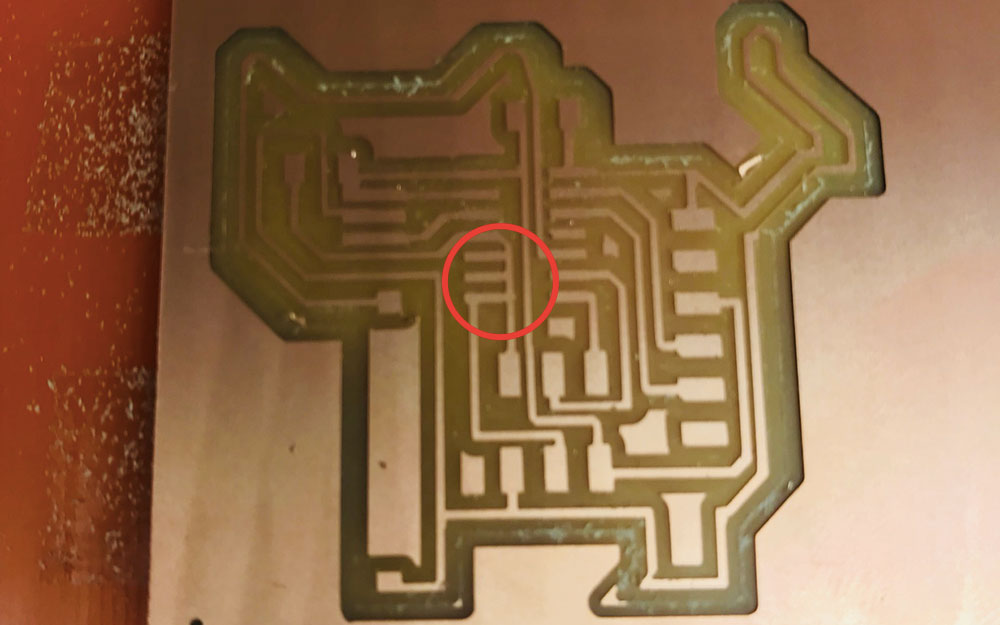 This trace was not supposed to be there
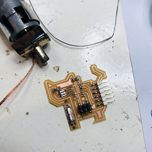
I used a hot air gun
I had to remove my ATtimy and scrape off the traces that wasn’t supposed to be there. This went ok. I used a hot air gun to heat the tin. I was holding on to the ATtiny and let gravity do its part.
I scraped the trace off and soldered the ATtiny back to the board. Now my board was a bit messy of all the tin from before. I tried to not use too much tin which later on resulted in that the pins weren’t connected properly (more about that later).
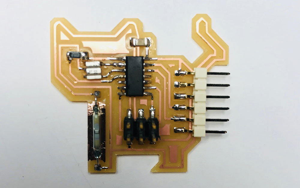 This is how my board looked before all the mess
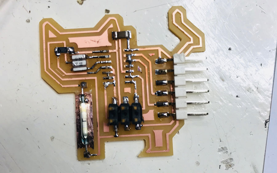 I removed the ATtiny
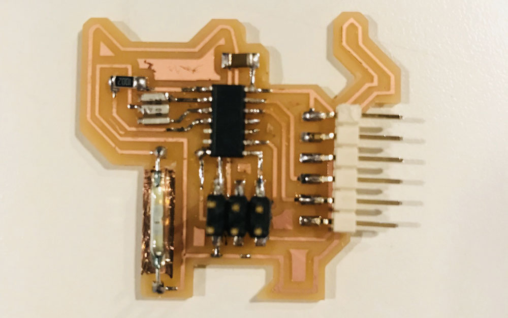 This is how my board looked after all the mess
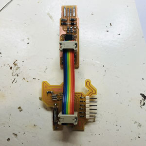
Connect the board to the programmer
Connection
The first time I tried to see if my programmer could see my board, that was when the extra trace still connected the four pins on the ATtiny. Next time was when I realized that I had too little tin, that the pins wasn’t connected to the pad. The third time it worked.
Program board
I decided to code in Arduino IDE. The code I created for my reed switch was a combination of the code I made before; making the LED blink and reading the serial monitor.
I had to include the library SoftwareSerial.h to be able to use the serial monitor. I set the receiving and transmitting pin. I set the pin number for the reed switch and a variable to read.
In the void setup I wrote the code for my reed switch being an input and specifying it to be a input pullup to activate the pullup resistor. And I set the serial begin to 9600 which corresponds to my computer.
In the void loop I identified the value to be the digital read of the reed pin and I also added code for the serial monitor to write the value.
#include //added a library to use the Serial Monitor
int rxPin = 0; //the receiving pin
int txPin = 1; //the transmitting pin
SoftwareSerial Serial(rxPin, txPin);
int REED = 3; // my reed switch is pin 3
int REED_value = 0; //variable to read the reed pin
void setup() {
pinMode (REED, INPUT_PULLUP); // my reed is an input (pullup)
Serial.begin(9600); // to enable communication, should correspond to serial monitor
}
void loop() {
REED_value = digitalRead(REED); // read the value of the reed
Serial.println(REED_value);
} 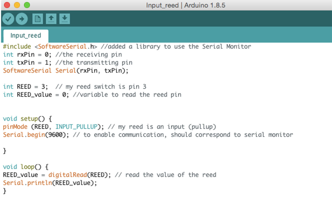 My code
Testing my input device
I connected my programmed board with the FTDI cable to the computer. I selected the port in the Arduino IDE and I could see the number "1" shown on the monitor. I used a magnet to test my reed switch. It worked! I noticed that the magnet need to be strong enough, how strong I don’t know since I didn’t test this. And it also needs to come from the right angle (at least if the magnet is as strong/weak as the one I used) to close the two switched; reeds.
Download files here
Schematic
Board design
Png trace file
Png cut file
Code
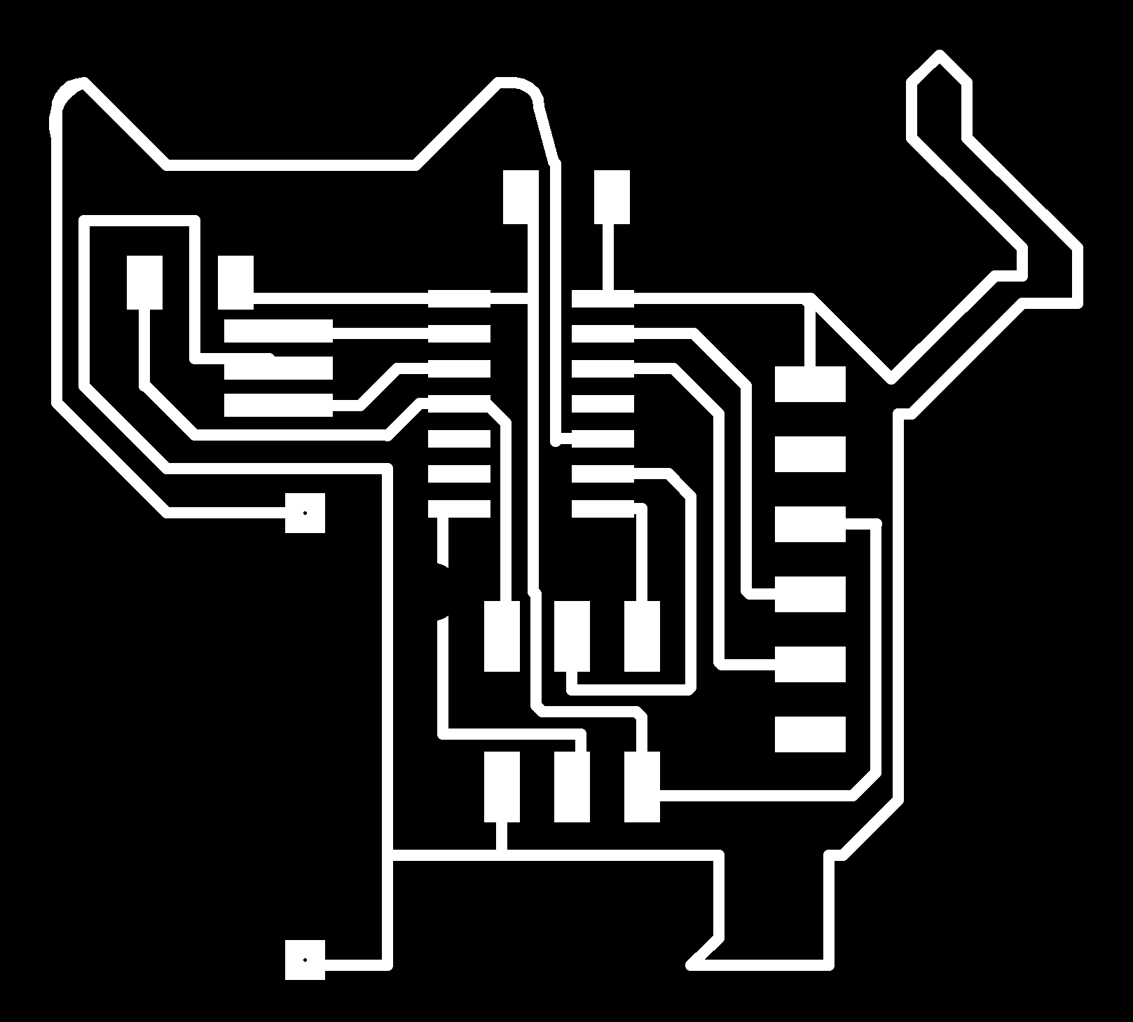
group assignment:
assignment: measure the analog levels and digital signals in an input device
Week 12: Output Devices
assignment: add an output device to a microcontroller board you've designed, and program it to do something
Like last week I wanted to learn something that would later be useful for my final project. I wanted to explore the RGB LEDs and see how they work. For power source, I was not going to use the USB on the computer again, but try an portable spruce. I’m not sure yet, but I think my power source for the interactive building blocks will be a 9V battery, so that’s what I went for this week too.
Eagle
I wanted to make two different boards, one with more or less only the LED and one with the rest. This to test the minimum size I could create.
This went really smooth, both the schematic and the board design. What I wasn’t aware of at this point was the wrong design of the LED icon in the board design which later on resulted in me making a new board.
Schematic main board
This is the list of components for the main board:
- 6-pin header
- Microcontroller ATtiny44A
- FTDI header
- 20 MHz resonator
- Resistor (10k)
- Reed switch
- Capacitor (1uF)
- 4 pin header for power
- Regulator
- Ground
- VCC
This is the list of components for the LED board:
- RGB LED
- Resistors x3
- 4-pin header
Milling
This also when really smooth I thought. But of course not. I had based my design on the cat board from last week, knowing that mods would leave a trace connecting some of the pins. I was just going to take them off after the cut. And I did, but in the wrong direction. I cut the trace off that I was going to leave. I must have been a bit tired.. So I just went ahead and cut a new board, this time taking the right trace off.
Soldering
Shiny and smooth as Neil would say! Good enough at least this time. My only obstacle was the direction of the LED. If I had looked closer, I would then have noticed that the icon for the LED was wrong and that I had to make a new board. But I didn’t notice this until starting to code and testing the board, when the wrong color was lit up.
The mistake
To walk through the whole process of what went wrong. There were two different board icons in the Fab library in Eagle, one big and one small. I didn’t know the difference, I should have done better research when choosing between the two, but I went for the one with big pads since that might be easier to solder.
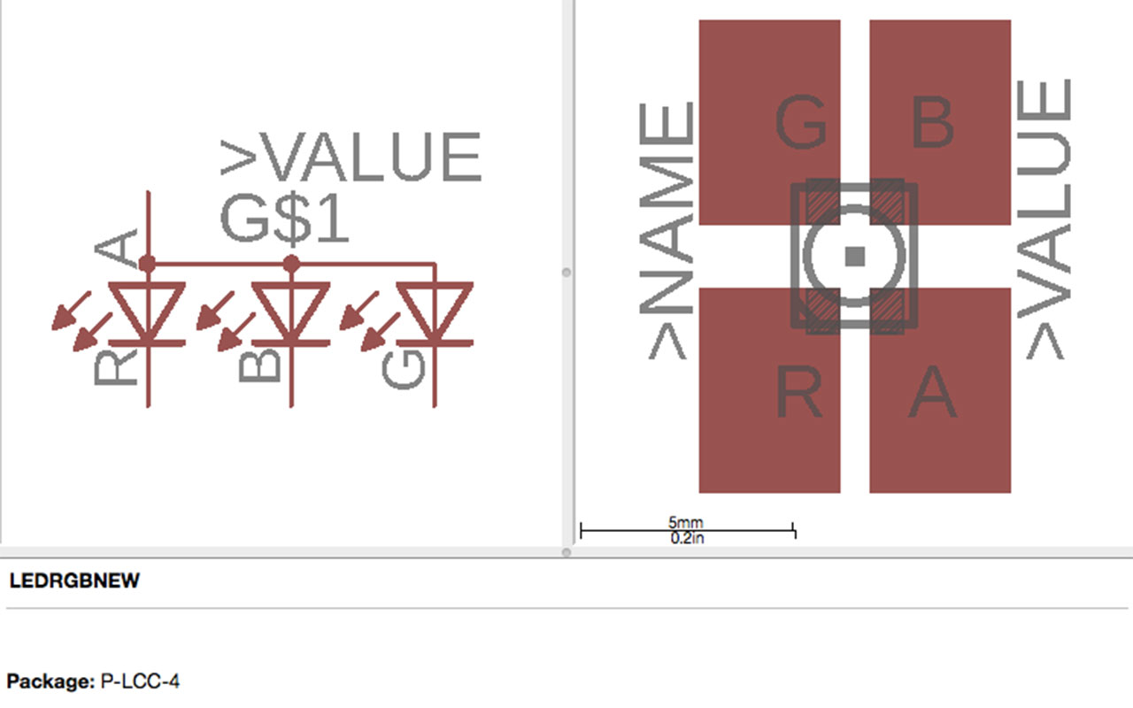 RGB LED with big pads
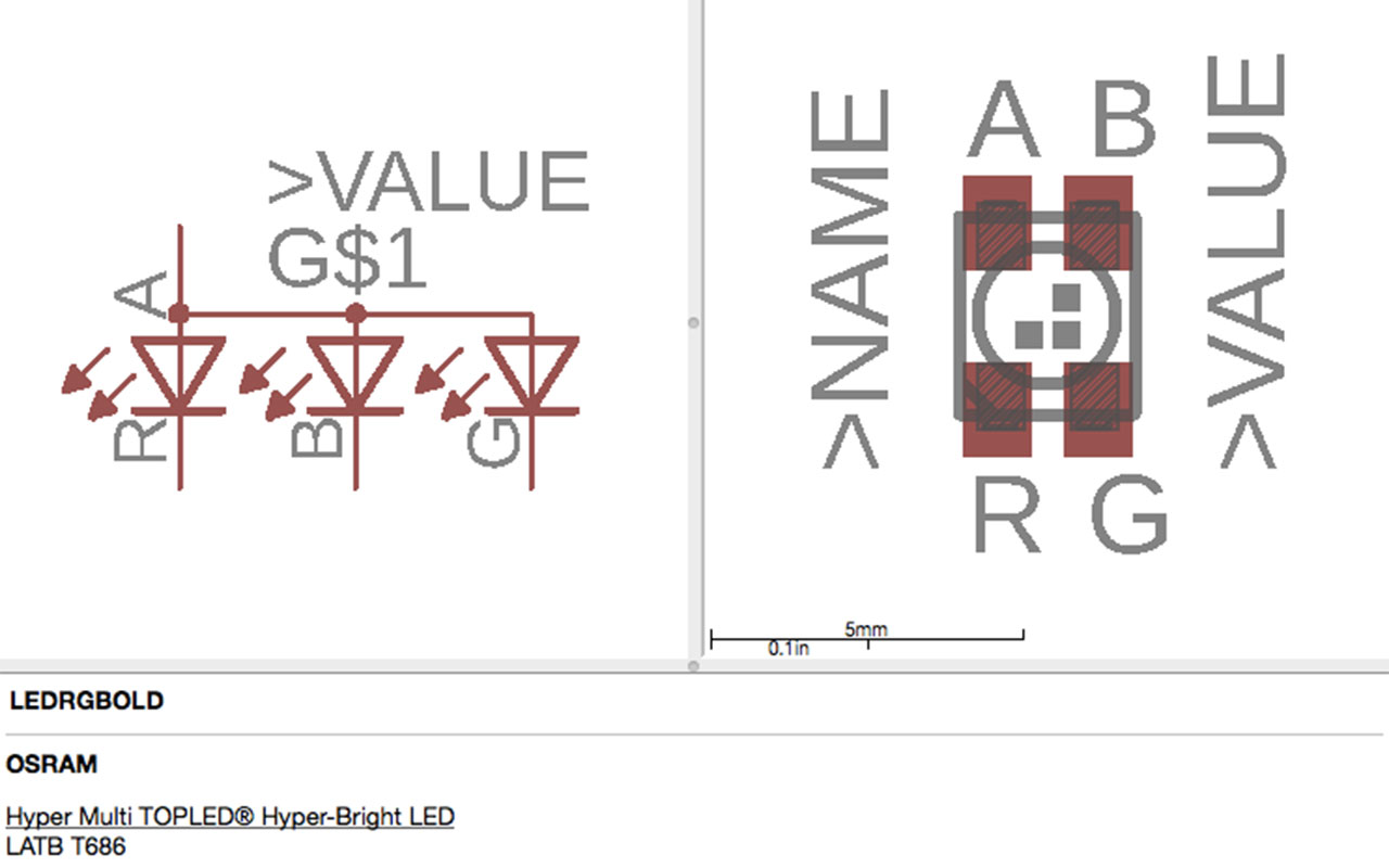 RGB LED with small pads
What I didn't see then, but what I see now, is that the orientation or the anode, red, green, blue pins is differnent in the two icons.
This is the RGB LED that I was going to use. It’s a so-called “common anode”. With a common anode the anode is connected to VCC and each individual LED to one resistor each that is then connected to an output pin. When coding and writing “LOW” to that pin, the LED will turn on, and “HIGH” will turn it off.
With the opposite, a “common cathode” the cathode is connected to GND and each LED’s anode through a resistor to the output pin. Then a HIGH turns the LED on.
On my board design, I had gotten the component icon from the library, and in that one, the corner mark wasn’t corresponding with the corner mark on the component itself. In the datasheet of the RGB LED it says in one place (very small, and not so clear) that pin 2 of the LED is the anode. This meant that my component had to be turned 180 degrees (from where the corner mark was - at the actual corner mark), but that also meant that my colors would be switched around and that the anode wasn’t connected to VCC anymore.
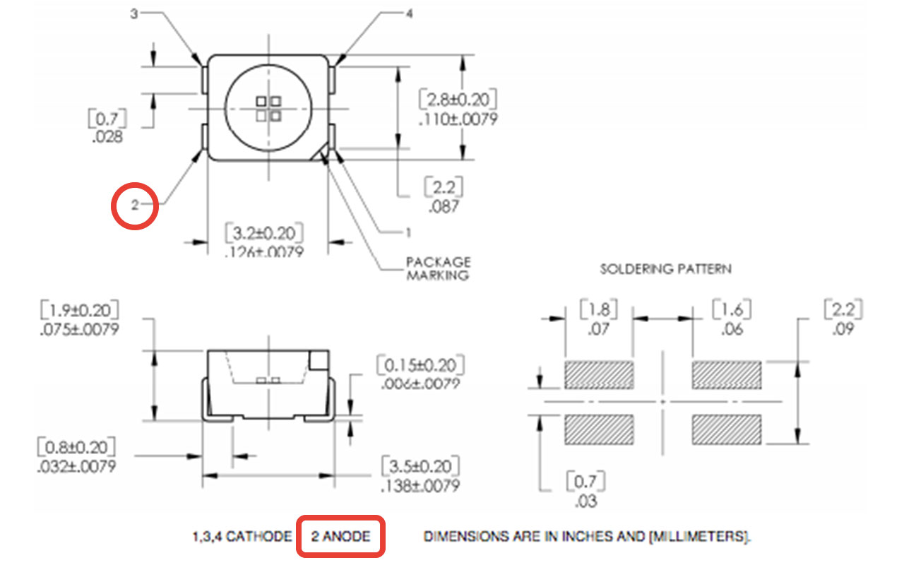 Pin 2 is the anode
Of course I didn’t notice this until much later, which meant that I had to go back to the schematic, pick the right icon, mill a new board and then solder it. I was a bit fast when doing this so I missed a trace, but I could easily fix that with some tin.
Calculate resistors for the LEDs
I should also mention that I calculated which resistors I should use for the board. I looked at the datasheet and found, “forward current” and “forward voltage”. I added the numbers for “typ” and the conditions used for typ in this wizard. As for “Source voltage” I wrote 5 since I was going to use a 9V battery but with a regulator making it to 5V.
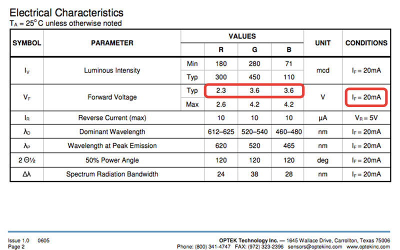 Forward current and forward voltage
- Red: 1/8W or greater 150 ohm resistor
- Green: 1/8W or greater 82 ohm resistor
- Blue: 1/8W or greater 82 ohm resistor
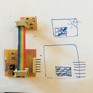
Orientation of connection
Testing the board and some simple code
As prior weeks, I checked if my computer could read my new board (the one with the ATtiny, not the LED board), and it could. In terminal I wrote the command that tells my programmer to look for ATtiny44, “avrdude -c usbtiny -p t44”. I then burned the bootloader since I had a new microcontroller and an external clock.
I used Arduino IDE this week too. I found some code in this tutorial that I wanted to try. But before this worked out for me, I had the whole mess with the wrong orientation of my LED and the board design, hence the connections to the pins.
Just a note about programming the ATtiny board that has a regulator to regulate a 9V battery to 5V. When using the USB, I had to be really fast uploading the code and taking the programmer out since the regulator gets really hot.
To test my LED I used this easy code below to test the different colors. This was when I noticed the connections were wrong.
int led_pin = 5;

void setup() {

  pinMode(led_pin, OUTPUT);
}

void loop() {
  digitalWrite(led_pin, LOW);
  delay(100);
}
Later on when I used my new board, with the right orientation, I saw from this code, the code that would make the LED lit up in six different colors that two colors were missing. Emma helped me out, telling me to check which pins on the ATtiny I had used. I had used one pin that wasn’t PWM which is the analog output. When designing the board I thought I was only going to use digital output (HIGH or LOW) but to change the brightness of the LED I need an analog output pin.

Color pattern
In this arduino tutorial it says: "Pulse Width Modulation, or PWM, is a technique for getting analog results with digital means. Digital control is used to create a square wave, a signal switched between on and off. This on-off pattern can simulate voltages in between full on (5 Volts) and off (0 Volts) by changing the portion of the time the signal spends on versus the time that the signal spends off. The duration of "on time" is called the pulse width. To get varying analog values, you change, or modulate, that pulse width. If you repeat this on-off pattern fast enough with an LED for example, the result is as if the signal is a steady voltage between 0 and 5v controlling the brightness of the LED."
This resulted in that my blue LED, could only have one brightness. Looking at the color pattern you could see that I will not be able to create purple and the aqua this way.
The code
I mentioned that I found a tutorial from which I used the code. But I wanted to really understand the code and what it would do.
First it was easy, I set the different pins. Pin 4 is not PWM but for next time using an ATtiny44 I will use any of the PWM pins: PA5, PA6, PA7, PA8 or PB2
int REDpin = 5; //my red light is pin 5
int GREENpin = 6; // my green light is pin 6
int BLUEpin = 4; //my blue light is pin 4
For the next part the tutorial said “If you are using a Common Anode RGB LED, then you need to change the analog write values so that the color is subtracted from 255, Uncomment the line #define COMMON_ANODE in the sketch!”
So I guess, since the common anode is connected in the opposite way, LOW being the LED off, the analog output probably function the same way. I was defining for the analogWrite how to translate the variables to suit the common anode output.
I also set the value for the variable setColor; red, green and blue. The function analogWrite is there to set the brightness off each LED, from 0-255. In the loop function, I can later on, set the amount of green, red and blue.
#define COMMON_ANODE

void setColor(int red, int green, int blue)
{
  #ifdef COMMON_ANODE
  red = 255 - red;
  green = 255 - green;
  blue = 255 - blue;
  #endif

  analogWrite(REDpin, red);
  analogWrite(GREENpin, green);
  analogWrite(BLUEpin, blue);
}
For the void set up I set the pinMode of each pin to be an output.
void setup() {
pinMode (REDpin, OUTPUT); //my red pin is an output
pinMode (GREENpin, OUTPUT); //my green pin is an output
pinMode (BLUEpin, OUTPUT); //my blue pin is an output

}
In the void loop I could, as mentioned decide the amount of brightness of each LED to set a specific color. Now knowing that my blue LED can’t change brightness I could try different colors mainly using the red and the green LED. The delay between the functions is to have a second between every new color.
void loop() {

  setColor(255, 0, 0);  // red
  delay(1000);
  setColor(0, 255, 0);  // green
  delay(1000);
  setColor(0, 0, 255);  // blue
  delay(1000);
  setColor(255, 255, 0);  // yellow
  delay(1000);
  setColor(80, 0, 80);  // purple
  delay(1000);
  setColor(0, 255, 255);  // aqua
  delay(1000);

}
The result
So my LED is working except the blue LED that can’t change brightness. I will remake the board during the week of networks and see how many LED boards I could connect to each other or explore in what outer way I can have multiple RGB LEDs in one of my interactive building blocks.
Download files here
LED board schematic
LED board design
main board schematic
main board design
LED board trace file
LED board cut file
Main board trace file
Main board cut file
Code
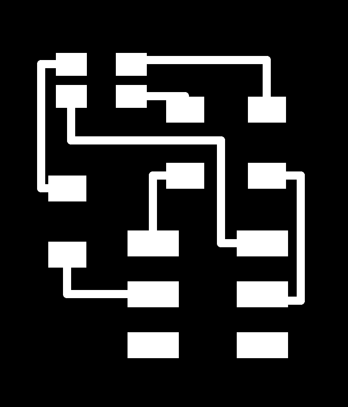
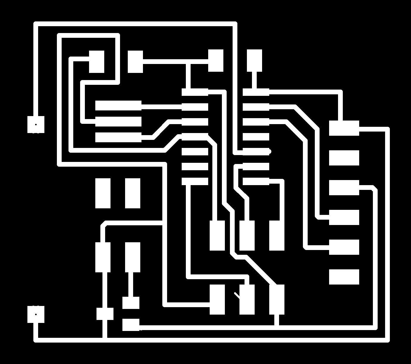
group assignment:
assignment: measure the power consumption of an output device
Week 13: Interface and Application Programming
assignment: write an application that interfaces with an input and/or output device that you made
I wish I had more time this week, this is a fun topic and it opens up lots of possibilities. I could only spend one day with this, so the result is fairly simple. But I will keep exploring this in the future!
Processing
I decided that I would do Processing this week. On Processing’s website, they say “Processing is a flexible software sketchbook and a language for learning how to code within the context of the visual arts.” It is free to download and it’s open source. I started off downloading the software for Mac. After that, I watched a bunch of tutorials made by this lovely charismatic man called Daniel Shiffman. I could marry that guy, so fun, humble and crazy! His “Hello Processing” tutorial is amazing! It’s great for a newbie like me, since he really explains everything from scratch. I also looked at some of the written tutorials on Processing’s website. This video series by Daniel Shiffman is also great. Watching tutorials was how I spent most of the time this week. You will see that from the result.
Program my input board (my Echo Hello board)
I decided to use my Echo Hello board this week. The board has a push button and a phototransistor, enough for me to test Processing for this week’s assignment. I decided that I wanted to create an interface for how long the button was pushed down. I wanted to create something that would change depending on the time.
Board over the Serial Monitor to Processing over the Serial Port
The workflow I will use is, first programming my board to do something. Then, connected it to the FTDI cable to read the serial monitor. Then, writing code in Processing, having it read the serial monitor to it’s serial port and make the interface do something.
But for this to work I need to make sure that I’m transferring the right values/numbers from serial monitor to Processing. And this is not as easy as it might seem. For example, having a digital read in your Arduino code, meaning the serial monitor will show either true or false; could be 0 and 1. When sending this data to Processing, the software will read the 0 and the 1 as chars, more or less characters. Those characters has an equivalent number which can be seen in an ASCII table. In the table we can see that 0 = 48 and 1 = 49.
About ASCII, Wikipedia says: ASCII, abbreviated from American Standard Code for Information Interchange, is a character encoding standard for electronic communication. ASCII codes represent text in computers, telecommunications equipment, and other devices. Most modern character-encoding schemes are based on ASCII, although they support many additional characters.
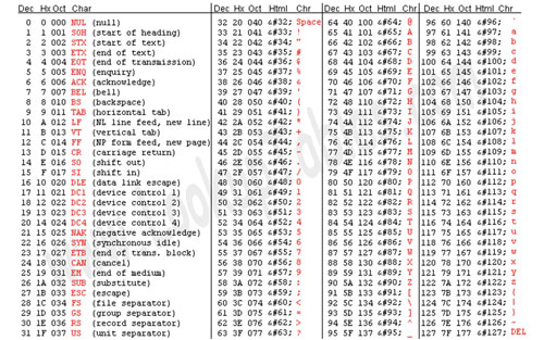 ASCII table
So to transfer the values right, there is different code that could be used, more about below.
Good-to-know-code
This is some good-to-know-code for two things; one is for helping Processing if the port can’t read any value, not to get a hiccup, and the other thing is that it transforms chars the integers, trimming the line, making it easy for Processing to read.
import processing.serial.*;

Serial myPort;   // Create object from Serial class

String val = "in";
int val_aux = 0;

void setup()
{
  myPort = new Serial(this, "/dev/cu.usbserial-FT9QO5SE”, 9600);
}

void draw() {
    if ( myPort.available() > 0) {  // if data is available
        val = myPort.readStringUntil('\n'); // read my port until \n symbol
        val = trim(val); // trim the line, removing everything that is not content

        if (val == null){ // if there is no value, the value is empty
          val = "UPS”; // give this value to not stop the process
        } else { // if it’s not empty
        val_aux = Integer.parseInt(val); // transform char to a integer, a real number
        }
 }

println(val_aux); // print the value
Program the board in Arduino IDE
I’m Arduino IDE, the code is the same as if I was to just program my board to do something. I will need to make sure that I have included the library for the serial monitor.
The code I was going to use is a version of this tutorial of making one button have the functionally of two or more. The tutorial explains the method of using the time for how long a button is pushed down to determine functions. My code would be a bit different, but this was a good start.
First I included the library SoftwareSerial.h to be able to use the serial monitor. I set the receiving and transmitting pin. I then set up a new serial object.
#include
#define rxPin 0
#define txPin 1
SoftwareSerial Serial(rxPin, txPin);
int pressLength = 0; //the value for how long the button is pushed down
int One = 100; //define the *minimum* length of time, in milli-seconds, that the button must be pressed for a particular option to occur
int buttonPin = 3; // button is on pin 3
void setup() {
pinMode(rxPin, INPUT); //rx is the input
pinMode(txPin, OUTPUT); //tx is the output
pinMode(buttonPin, INPUT_PULLUP); //the button is a input pullup (to activate internal resistor)
Serial.begin(9600);
}
void loop(){
while (digitalRead(buttonPin) == LOW ){
delay(100);
pressLength = pressLength + 100;
}
if (pressLength >= One){
Serial.println(pressLength);
}
pressLength = 0; //reset the pressLength every loop
} 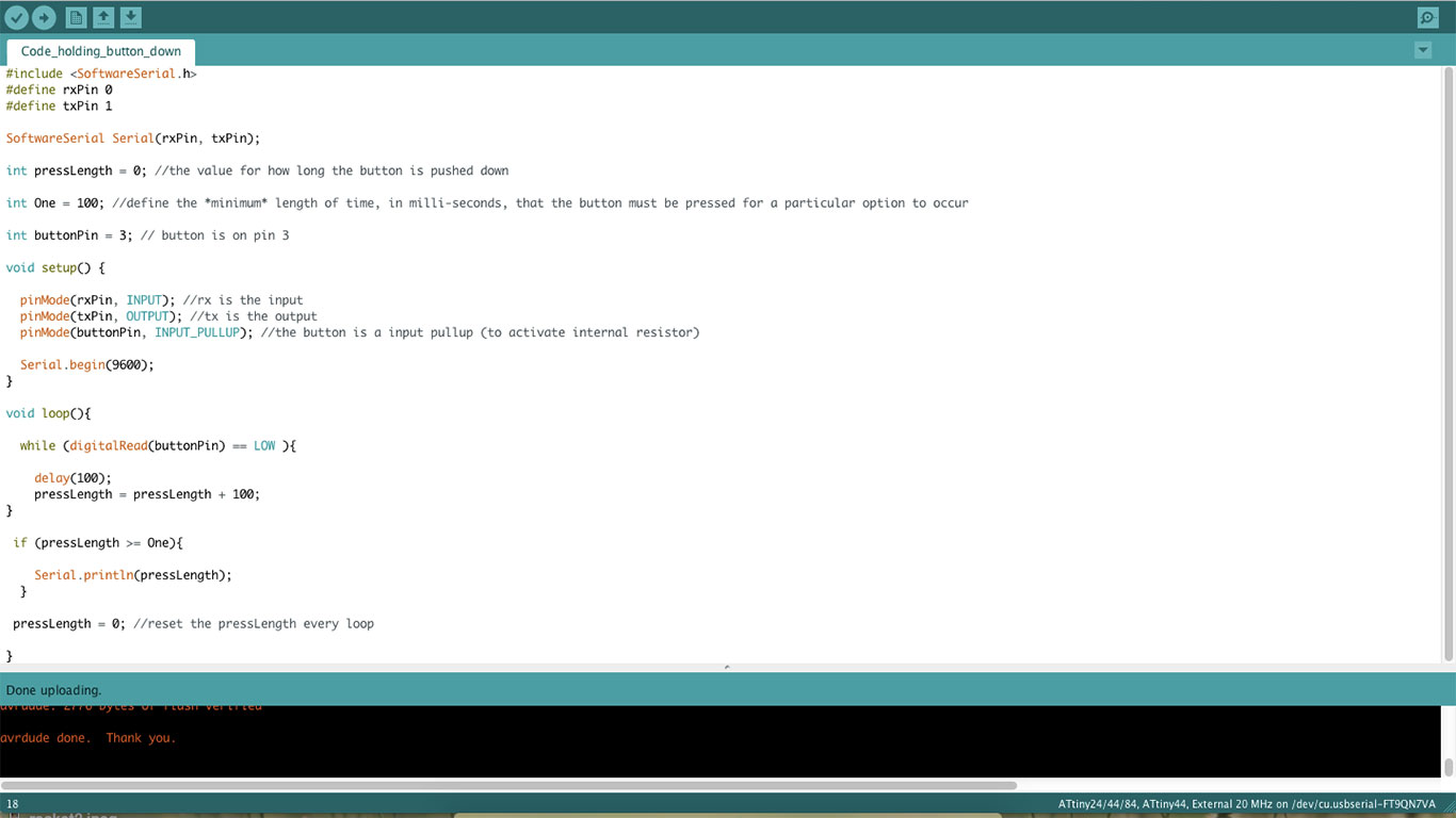 Code
Code
Alternativ code that print every value while pushing down the button
#include
#define rxPin 0
#define txPin 1
SoftwareSerial Serial(rxPin, txPin);
int pressLength = 0; //the value for how long the button is pressed down
int buttonPin = 3; // button is on pin 3
void setup() {
pinMode(rxPin, INPUT); //rx is the input
pinMode(txPin, OUTPUT); //tx is the output
pinMode(buttonPin, INPUT_PULLUP); //the button is a input pullup (to activate internal resistor)
Serial.begin(9600);
}
void loop(){
while (digitalRead(buttonPin) == LOW ){
delay(100);
pressLength = pressLength + 100;
Serial.println(pressLength);
}
if (digitalRead(buttonPin) == HIGH ){
}
pressLength = 0; //reset the pressLength every loop
} 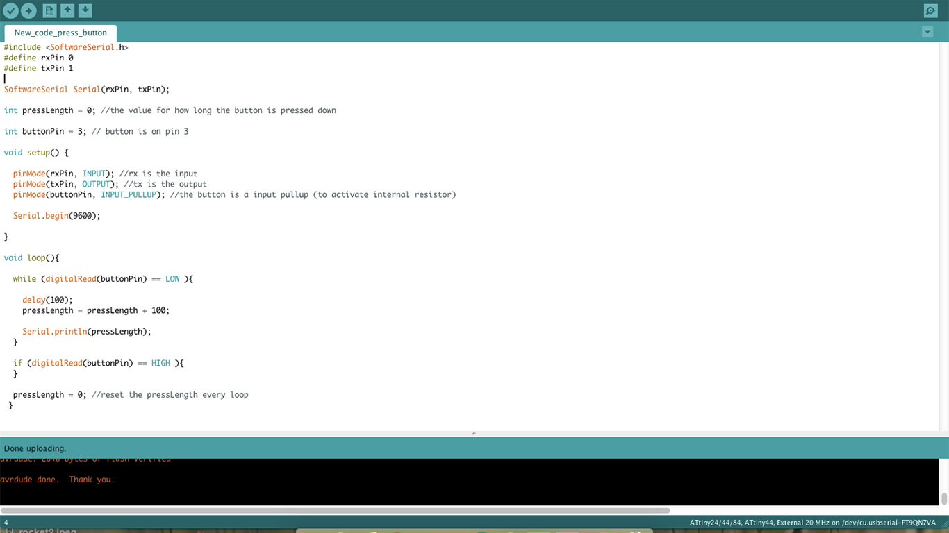 Alternative code
Serial monitor in Arduino IDE
I uploaded the code and tested the result in the serial monitor. It was showing the value of how long I was pushing down the button. In the first code it showed the value first when I let go of the button, and in the second code it showed how long the button was pressed down while pressing.
Processing
The Processing software has a similar interface to Arduino IDE. Just like Arduino has setup() and loop(), Processing has setup() and draw() (instead of loop).
Before the setup, just like in Arduino IDE I need to import the library processing.serial.*. Then, to be able to listen in on a serial port on our computer for any incoming data I created a Serial object. I also added a value to receive the data coming in.
import processing.serial.*;

Serial myPort;   // Create object from Serial class
String val = "in";     // Data received from the serial port
int val_aux = 0;
For the setup I set the serial port that the board is connected to and set up our Serial object to listen to that port. In the setup I also set the size of the interface window, but more about that later.
void setup()
{
  myPort = new Serial(this, "/dev/cu.usbserial-FT9QO5SE", 9600);
  size(500, 500);
}
In draw I used the code that Emma taught us that help the process if the port can’t read any value, just like I explained earlier in the “good-to-know-code”.
void draw(){
if ( myPort.available() > 0) { // If data is available
val = myPort.readStringUntil('\n'); // read my port until \n symbol
val = trim(val); // trim the line, removing everything that is not content
if (val == null){ // if there is no value, the value is empty
val = "UPS”; // give this value to not stop the process
}
}
else { // if it’s not empty
val_aux = Integer.parseInt(val); // transform char to a integer, a real number
println(val_aux); //print value
}
}
}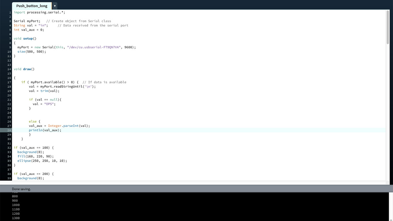 Code Processing
With this code my port could read the data from my board. But nothing would happen. So in the if-statement I wrote some simple code for how a circle would appear in the interface when pressing the button. If pressing the button longer, the circle became bigger.
The code says, if the value is equal to a value, for example 100, then the background should turn black. The background goes back to black every time I press the button so the circles do not appear on top of each other. Then the fill which sets the color of the circle. And then the size and the position of the circle (or ellipse as Processing calls it). In the setup I had set the size of the interface window to size(500, 500);. In the last circle, the one when you push the button for a long time, I added a text and made the circle red.


if (val_aux == 100) {
  background(0);
  fill(160, 220, 90);
  ellipse(250, 250, 10, 10);
}

if (val_aux == 200) {
  background(0);
  fill(160, 220, 90);
  ellipse(250, 250, 40, 40);
}
if (val_aux == 300) {
  background(0);
  fill(160, 220, 90);
  ellipse(250, 250, 70, 70);
}

if (val_aux == 400) {
  background(0);
  fill(160, 220, 90);
  ellipse(250, 250, 100, 100);
}

if (val_aux == 500) {
  background(0);
  fill(160, 220, 90);
  ellipse(250, 250, 130, 130);
}

if (val_aux == 600) {
  background(0);
  fill(160, 220, 90);
  ellipse(250, 250, 160, 160);
}
if (val_aux == 700) {
  background(0);
  fill(160, 220, 90);
  ellipse(250, 250, 190, 190);
}

if (val_aux == 800) {
  background(0);
  fill(160, 220, 90);
  ellipse(250, 250, 220, 220);
}
if (val_aux == 900) {
  fill(160, 220, 90);
  ellipse(250, 250, 250, 250);
}
if (val_aux > 900) {
  background(0);
  fill(255, 0, 0);
  ellipse(250, 250, 500, 500);

	textSize(150); // Set text size to 32
	fill(0, 0, 0);
	text("BOOM", 25, 300);
	}
}
Download files here
Code Arduino IDE
Alternative code Arduino IDE
Processing code
group assignment:
assignment: measure the power consumption of an output device
Week 14: Networking and Communications
assignment: design and build a wired and/or wireless network connecting at least two processors
Again I had too little time to make something more interesting than making a LED blink. But again, hard enough! I had so many challenges this week, mainly regarding what I was actually doing. I have been following several different tutorials and none of them have had the same structure or ways of doing things. In the end, I figured it all out, but it took some time.
It's about networking and communications this week. I decided to try out I2C since it allows you to connect many slaves to a master with only two pins. Sparkfun explains I2C like this: “The Inter-integrated Circuit (I2C) Protocol is a protocol intended to allow multiple “slave” digital integrated circuits (“chips”) to communicate with one or more “master” chips. Like the Serial Peripheral Interface (SPI), it is only intended for short distance communications within a single device. Like Asynchronous Serial Interfaces (such as RS-232 or UARTs), it only requires two signal wires to exchange information.”
To start off easy I decided to make only two boards, one master, and one slave. I wanted the slave to have a LED that the master could turn on and off. And when the LED was on or off I wanted the slave to send a message back to the master’s serial monitor saying if the LED was on or off.

I2C
Making the boards
I used Eagle, as usual, making the schematic and the board design. This went really smooth. I followed this site as a reference. My boards are fairly simple with as few components as possible. I have mainly been using ATtiny44’s in the previous project, so I went with that again. If I would have known what I know today, I would probably be using an ATtiny45 instead since there are more libraries to choose from. The Fablab was out of ATtiny44 so I used ATtiny84 instead, but they are the same.The pins used or the I2C signals are SCL and SDA. SCL is the clock signal, and SDA is the data signal. It is very important to use a pullup resistor for both these signals. This is to restore the signal to high when no device is asserting it low.
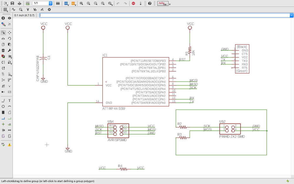 Schematic master
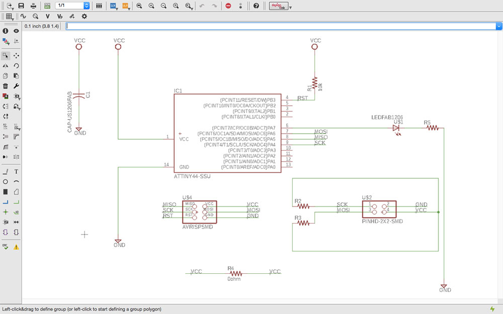 Schematic slave
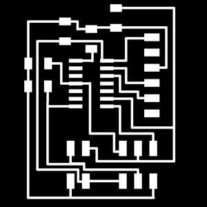 Master trace
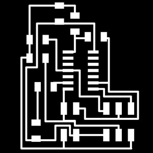 Slave trace
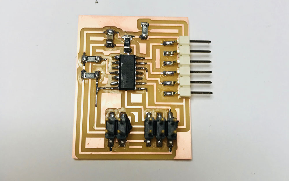 Master board
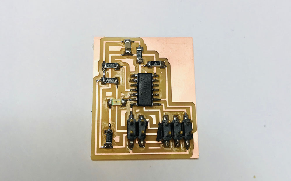 Slave board
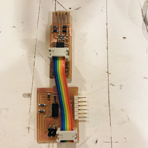
Connect to programmer
Testing the boards with simple code
When the boards were designed, milled and all components were soldered on, I tested if my programmer could see the two boards, typing “avrdude -c usbtiny -p t84” in Terminal.
Before even going inte I2C code, I used very simple code to test the serial monitor on the master board and if the LED could blink on the slave board. This worked, so I knew that the boards were working fine.
Simple code for the master serial monitor:
#include
#define rxPin 0
#define txPin 1

SoftwareSerial serial(rxPin, txPin);

void setup() {

pinMode(rxPin, INPUT);
pinMode(txPin, OUTPUT);
serial.begin(9600);

}

void loop(){
serial.println("the serial monitor is working");
//serial.println(value_L_sensor);

delay(1000);
}
Since I have no 20 MHz resonator on this board, I have no external clock. I had to change the settings in Arduino IDE to internal 8 MHz clock. I also made sure all the other settings were correct, the board set to an ATtiny84, Processor to ATtiny84, and the right programmer. When I was sure, I burned the bootloader. This is important that I change next time using a external clock of 20 MHz since the settings stay with what it was saved with last.
Simple code for the slave LED:
int led_pin = 7;
void setup() {
pinMode(led_pin, OUTPUT);
}
void loop() {
digitalWrite(led_pin, HIGH);
delay(100);
digitalWrite(led_pin, LOW);
delay(100);
}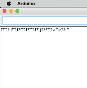 When the clock was wrong
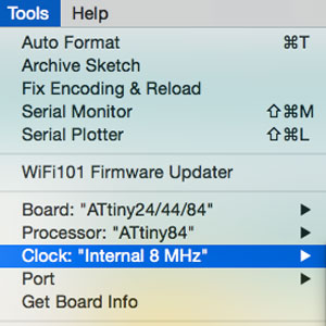 Change clock settings
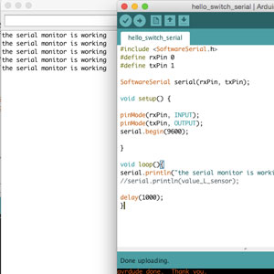 Serial monitor is working
Adding libraries
To have the master talking to the slave using I2C I needed to download libraries to be used in Arduino IDE. This was a bit hard, many libraries were not recommended for ATtiny84 hench not compatible. I soon found a suitable master library, I would have love one library for both the slave and the master, but I couldn't find that for the ATtiny84. Also, when googling, I read things like “the AtTiny84 doesn't have hardware TWI. You need to use i2cMaster.S which implements a software master.” To be honest, I still don't know what this means except that I had to find a suitable library for the slave. I ended up with this one that worked really well. For the master, I used this one.
To add a library, in Arduino IDE, go to “Sketch”, “Include library” then “Add ZIP-library”. In the folder, add the downloaded ZIP-file. Then go back to “Sketch”, “Include library” and click “Manage Libraries…”. Search for your library and click to install. Sometimes you need to restart the software for the libraries to appear in the list of options.
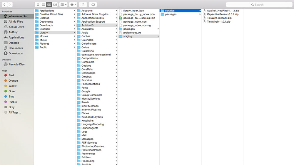 Folder where to find libraries
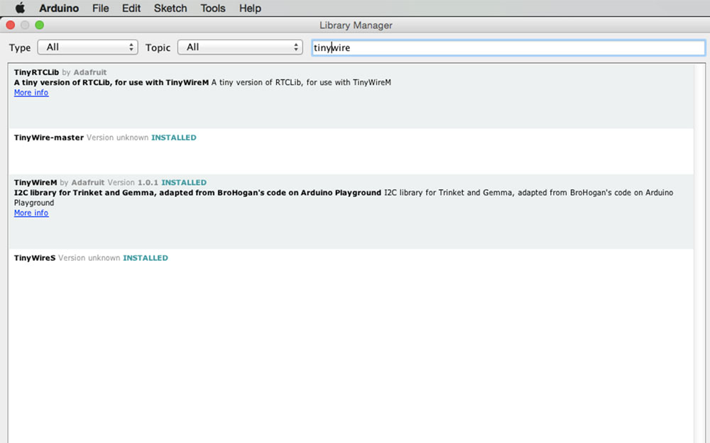 Manage Libraries
Final code
My final code is a version of this one and this one from former Fab Academy students, mainly the first one from Teo Cher Kok.Master
First I added the library TinyWireM.h and then I defined the address that I was going to use for the slave. I don’t think it’s necessary to define the master, but I decided to do that to make it easier for me to keep them apart.
#include  //include the library
#define device (1) //define master
#define SLAVE_ADDRESS 0x6 //define the address for the slave
Since I wanted to use the serial monitor I had to add that library and define the pins.
#include //add library to be able to use the serial monitor
int rxPin = 0; //the receiving pin
int txPin = 1; //the transmitting pin
SoftwareSerial serial(rxPin, txPin); // to set up the serial object
In I2C, the void setup requires a initialization. The command "begin" is used. Then I set the code for the serial monitor.
void setup() {
TinyWireM.begin();//setup initialization

pinMode(rxPin, INPUT); //the rx pin is the input of the communication
pinMode(txPin, OUTPUT); //the tx pin is the output of the communication
serial.begin(9600); //begin communication with computer
}
In the void loop I set what the master will communicate to the slave. The master will send "1" and "0" to turn the LED on or off on the slave board. The slave will then send a message to the master telling if the LED is on or off through the serial monitor.
The loop commands below are all standard commands for I2C and for the communication to start and end.
TinyWireM.beginTransmission(SLAVE_ADDRESS);/
TinyWireM.send
TinyWireM.endTransmission()
The I2C protocol might give a better understanding. This text is from and this tutorial “Messages are broken up into two types of frame: an address frame, where the master indicates the slave to which the message is being sent, and one or more data frames, which are 8-bit data messages passed from master to slave or vice versa. Data is placed on the SDA line after SCL goes low, and is sampled after the SCL line goes high. The time between clock edge and data read/write is defined by the devices on the bus and will vary from chip to chip.”
void loop() {
TinyWireM.beginTransmission(SLAVE_ADDRESS);//begin transmission to slave address
TinyWireM.send(1);//send "1"
TinyWireM.endTransmission();//end the transmission
msg();//receive message
delay(2000);//wait 2000 millisec

TinyWireM.beginTransmission(SLAVE_ADDRESS);//begin transmission to slave address
TinyWireM.send(0);//send "0"
TinyWireM.endTransmission();//end the transmission
msg();//receive message
delay(2000);//wait 2000 millisec
}
For the master to pick up a message from the slave, I added the command “msg();” which is defined in the void msg.
First I make sure to set the message to be treated as a variable. Then the setting for the master to request a message from the slave, making sure I type the right name of the slave. Then, to make sure the master is available when the slave is sending the message, I added an if-function. Then the actual if/else if message saying what the serial monitor should write depending on the message sent from the slave.
void msg()
{
volatile byte msg =0; //treat as variable
TinyWireM.requestFrom(SLAVE_ADDRESS,1);//request from slave address

if (TinyWireM.available()){ //to make sure the master is available
msg = TinyWireM.receive();//receive message

  if (msg ==4){//if this message
  serial.println("Slave LED off");}//print this in serial monitor
  else if (msg ==5){//if this message
  serial.println("Slave LED on");}//print this in serial monitor
  }
}
Slave
The code for the slave was a bit more straightforward. At first, I included the library for the slave and defined the address of the slave. I also set the pin for the LED.
#include //include the library
#define I2C_SLAVE_ADDRESS 0x6//define the address for the slave

int LED = 7;
In void setup, it is similar to the master code. First, a command telling the slave it is a slave and initializing the setup. The pinmode for the LED also need to be set in the setup.
In the void loop, similar to the master code, I need to tell the slave to treat the message as a variable. Then again, setting an if/else-command, saying if the slave is available, the slave should receive bytes from the master. If the bytes are equal to 0x01, the LED should be turned off and the message sent to the master should be “4”. Else, the LED should be turned on and the message sent to the master should be “5”.
void loop()
{
  byte byteRcvd =0;
  volatile byte msg =0;//treat as variable
  if(TinyWireS.available()){ //if input and slave available
      byteRcvd = TinyWireS.receive(); //receive from master

      if (byteRcvd == 0x01){ //if bytes received
      digitalWrite (LED, HIGH); //turn off LED
      TinyWireS.send(4);//send message
    }
      else {
      digitalWrite (LED, LOW);//turn on LED
      TinyWireS.send(5); //send message
      }
}
Download files here
Master trace
Master cut
Slave trace
Slave cut
Master board design
Master schematic
Slave board design
Slave schematic
Simple code LED
Simple code serial monitor
Master code
Slave code
.png)
.png)
.png)
.png)
Week 15: Mechanical Design
assignment: design a machine that includes mechanism, actuation and automation. Build the mechanical parts and operate it manually
Finally a real group assignment! I love working together with others! Sadly it happened to be the week that I had to go home to Stockholm, so the collaboration part was a bit harder than it could have been.
Brainstorming
Since we are a big group in Amsterdam, we decided to create two teams. First, we brainstormed in the big group to later decide the two smaller groups. Very early in the brainstorming session, we noticed that we all wanted to do something silly and fun, not necessarily the most useful machine. Ideas like a karaoke machine, Neil bingo, and engraving cheese came up. One idea stuck a bit more with me. It was the Dutch lunch generator. If you have ever been in the Netherlands, you know that Dutch people many times eat sandwiches for lunch. What they put on the sandwiches differs from chocolate, minced raw meat, cheese, etc. Me, Henk, Jelka, and Hanna decided to go ahead and create a random Dutch lunch generator.
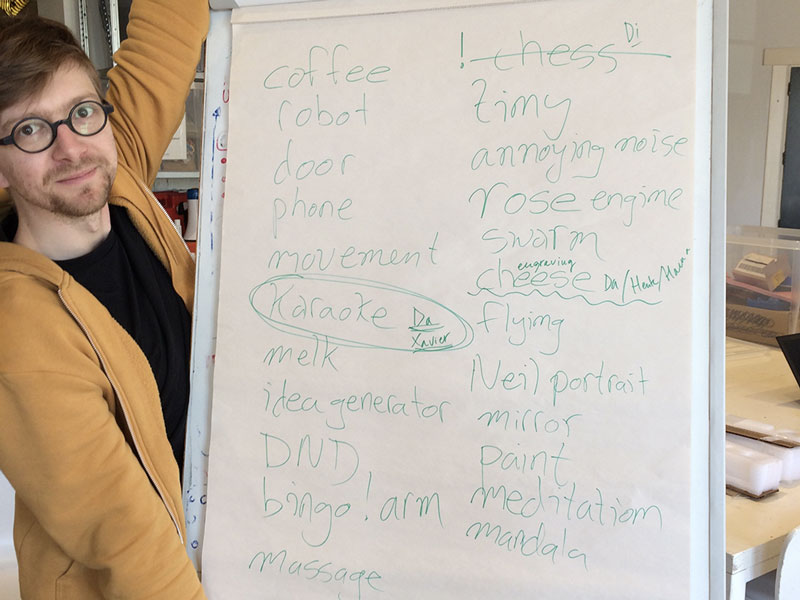 Brainstorming in the big group
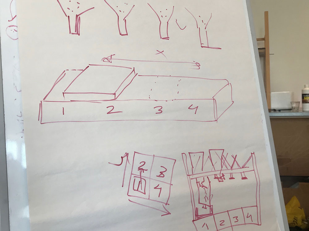 Brainstorming ideas
Random Dutch lunch generator
The machine will help you decide the topping on your sandwich, randomly, and in combinations that you might otherwise wouldn’t have thought of. The bread piece will be placed in a lunchbox that is already standing under the different toppings. Exactly how the random generator will start is not decided yet, but the idea is that a motor will act accordingly to code that is randomizing the different sections of the stage and then opening up the respective funnel that is stopping the topping from coming out.
We decided to divide the work between us; I was going to build the stage, Jelka the construction over the stage, holding up the topping funnels, Henk would create a construction that could turn tubes so that we could have some tube toppings as well, and Hanna would create the construction for the topping funnels and their respective motor.
Creating the stage and the overall construction
Before starting designing the stage, I had a look at some of the previous student’s work. Emma had also shown us a modular system for stages. However, we decided fairly early that we wanted to work with MDF, and the folding versions of stages would only work with cardboard. I found this tutorial from previous years. They had made a design in MDF that looked similar to what we wanted to do. The also had a downloadable version of their design.
I downloaded the file and started making some changes in Ilustrator. The team had decided on some measurements for the machine, and for some reason, I must have gotten them really wrong. However, we didn’t notice this until much later when the stage was cut and assembled. Which resulted in Hanna and Jelka re-doing the design when I was away in Stockholm. Blessing in disguise, I got to help when I got back since the file had minor mistakes and we also decided to make a few tweaks to it.
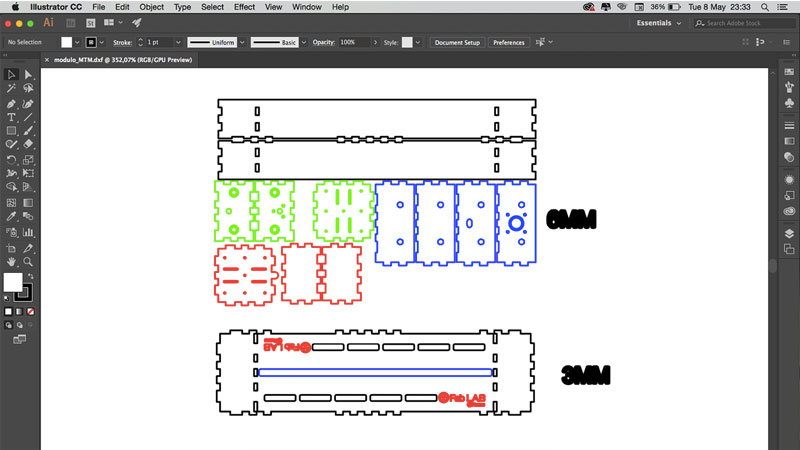 Original file in Illustrator
To walk through the processes of re-designing and cutting the stages
- I exported the dxf file.
- My Fusion 360 was not happy with me at that moment, and decided to be slow and shut itself off. For that reason, I decided to make the alterations in Illustrator.
- The design was for 6mm MDF, and we were going to use 3mm, hence I had to change all the slots.
- Before changing them all, we did a kerf test. We made three different material thickness; 3mm, 3,2mm, and 3,5mm. All of them had the same slot width hench good press-fit, but the slots with the material thickness of 3,2mm looked the best.
- I changed the slot depth, the material thickness, on all slots and changed the size of the holes. I also took away parts that we were not going to use. This took longer than expected since I had to do every single piece.
- When the design was done, I changed the stroke size to 0,1 and saved the file as an Illustrator CS6 file.
- I uploaded it to the laser cutting software and made sure everything was correct.
- I placed the material on the bed and made a test run for the design. It all looked good.
- I used the settings Power: 45 and Speed: 100 for the cutting.
- Then I pressed start and the cutting went well.
- I assembled the parts and noticed a mistake. The green parts in the picture weren’t cut off. I decided to wait with fixing that, and maybe even do it by hand. This wasn't necessary since we re-did the whole design.
- Then we noticed that the design was too big. Actually twice, which resulted in us doing this process two times more. The first stage was just too big, the second one we figured that there was no “motor screw” long enough, and the length of our design would look unsymmetric.
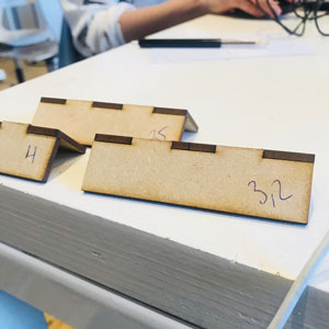 Slot test
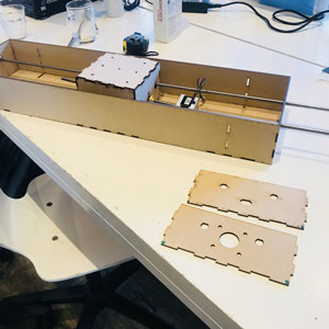 First stage that was too big
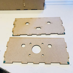 Design mistake
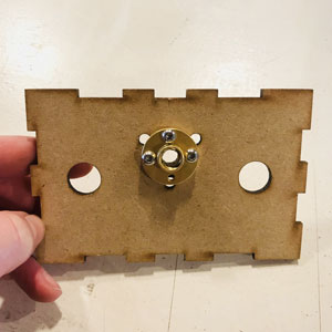 The wrong holes for linear bearing
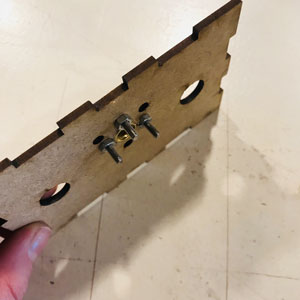 Attached
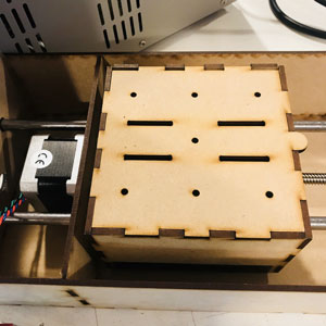 In place
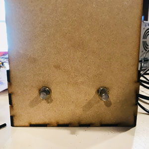 Glued to stay in place
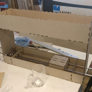 Assembled-ish
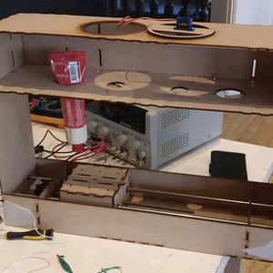 Assembled-ish
Download files here
Stage parts in Illustrator (top part not right length)
Stage parts DXF
Original stage file
group assignment:
assignment: same as individual assignment
Week 16: Machine Design
assignment: actuate and automate your machine and document the group project and your individual contribution
The second week of making a machine! We left off somewhere having the machine work manually. We could turn the screw on the motor to make the movable part on the stage go from one side to another. Now it was time to automate it!
Motor, Arduino Uno, CNC shield and motor drivers
The motor that we are going to use is a Pololu stepper motor, NEMA 17. It is bipolar, is has a 1.8° step angle, meaning it has 200 steps/rev. Each phase draws 1.7 A at 2.8 V. All this can be read in the datasheet on this site.
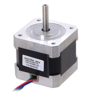
Pololu stepper motor, NEMA 17
Just a quick overview of what a stepper motor is. I found this great explanation on learn.adafruit; “Stepper motors are DC motors that move in discrete steps. They have multiple coils that are organized in groups called "phases". By energizing each phase in sequence, the motor will rotate, one step at a time. With a computer controlled stepping you can achieve very precise positioning and/or speed control.”
In this assignment, we are allowed to use an Arduino to run our machine. I was really happy to work with an Arduino Uno and it was interesting to better understand an Arduino CNC Shield and Stepper Motor Drivers that was going to run the three stepper motors. I did not work with the two server motors that we used for the funnels, those were connected directly to pins on the Arduino Uno.
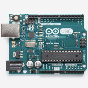 Arduino Uno
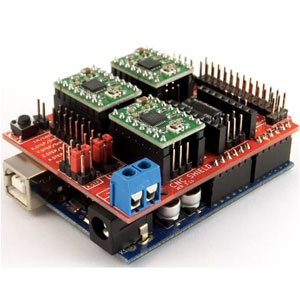 Arduino CNC Shield
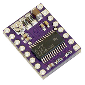 Stepper Motor Drivers
I attached the CNC Shield to the Arduino Uno. The CNC shield takes the trouble out of doing own hardware layout, it can host four different stepper motors. The CNC shield also allows high external power supply for powering the motors. It’s very important to get the orientation right; the USB port on the Arduino should be on the same side as the power supply on the CNC Shield. The power supply wire can be connected to the 12V power source.
Next, I connected the motor drivers DRV8825 on to the CNC shield. Again it’s important to get the orientation right; the potentiometers should be on top in the orientation of the Arduino. What the DRV8825 does is that it allows higher resolutions by allowing intermediate step locations, which are achieved by energizing the coils with intermediate current levels.
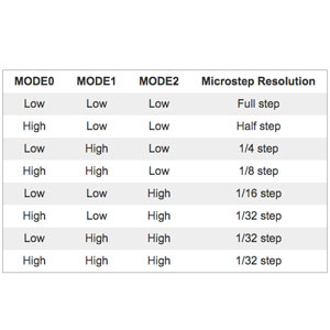
Step-modes
Under the motor driver chips I added three jumpers per motor driver. The jumpers enable the different current levels which result in the different step-modes, as shown in the table. With all three jumpers, i.e. all three microstep selection pins connected, the result is a 1/32 step-mode. The 1/32 step-mode means 6400 microsteps per revolution (200x32). This I learned from the product page earlier referred to.
Before going further me and Henk had to set the current limitation.
Set the current limit on the stepper motor
This site explains really well why you want to set the current limitation on the stepper motor. It says: “To achieve high step rates, the motor supply is typically much higher than would be permissible without active current limiting. For instance, a typical stepper motor might have a maximum current rating of 1 A with a 5Ω coil resistance, which would indicate a maximum motor supply of 5 V. Using such a motor with 12 V would allow higher step rates, but the current must actively be limited to under 1 A to prevent damage to the motor.” All in all, this means that you can use voltages above the stepper motor’s rated voltage to achieve higher step rates, which in turn means that you can achieve higher speed to send the step pulses to the motor driver.
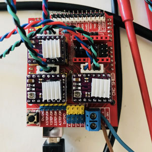
All three stepper motors connected
I used a power source, a multimeter a small screwdriver to set the current limit. In our case the power source was broken, so we had to use an extra multimeter to measure the voltage from the power source.
To set the current limitation you trim the potentiometer or the board. Me and Henk did this together since someone has to look at the multimeter and turn the screwdriver, and the other one needs to hold the multimeter and make sure not to create any shorts. We set the three potentiometers to approx 0.8 V referring to David’s calculations. David writes: “The Pololu page states that the motor driver can supply 2.2A per coil, and the motor's datasheet wants 1.68A per coil. Pololu gives this equation for calculating the current: Current Limit = VREF × 2, by measuring the voltage at the VREF via on the board (or the video shows a trick of clipping the lead of the multimeter to the screwdriver turning the current-limiting trimpot). The desired current is 1.68 A, so VREF should read 1.68/2 = 0.84V.”
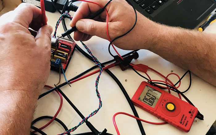 Setting the current limitation
Jumpers broken
Something was very wrong when doing this, the multimeter went down to zero every time we did the measurement. I figured out that something must be wrong with the hardware, and after a while, I saw that one of the jumpers were broken. I replaced it and now it worked fine.
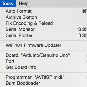
In Arduino IDE
Test the stepper motors
I had gotten some example code from Emma that I tried out to see if it could run the three motors at the same time. I plugged the Arduino to the computer with the USB cable and uploaded the code using Arduino IDE as usual. What I first forgot was to change the settings in Arduino IDE, that I now was using an Arduino Uno and the programmer “AVRIPS mkll”.
I will explain the final code below which includes this code too, hence no explanation of the code.
#define EN        8

//Direction pin
#define X_DIR     5
#define Y_DIR     6
#define Z_DIR     7

//Step pin
#define X_STP     2
#define Y_STP     3
#define Z_STP     4

//DRV8825
int delayTime=30; //Delay between each pause (uS)
int stps=6400;// Steps to move

void step(boolean dir, byte dirPin, byte stepperPin, int steps){

  digitalWrite(dirPin, dir);

  delay(100);

  for (int i = 0; i(symbol less than)steps; i++) {

    digitalWrite(stepperPin, HIGH);
    delayMicroseconds(delayTime);
    digitalWrite(stepperPin, LOW);
    delayMicroseconds(delayTime);
  }
}

void setup(){

  pinMode(X_DIR, OUTPUT); pinMode(X_STP, OUTPUT);
  pinMode(Y_DIR, OUTPUT); pinMode(Y_STP, OUTPUT);
  pinMode(Z_DIR, OUTPUT); pinMode(Z_STP, OUTPUT);

  pinMode(EN, OUTPUT);

  digitalWrite(EN, LOW);
}

void loop(){

  step(false, X_DIR, X_STP, stps); //X, Clockwise
  step(false, Y_DIR, Y_STP, stps); //Y, Clockwise
  step(false, Z_DIR, Z_STP, stps); //Z, Clockwise

  delay(100);

  step(true, X_DIR, X_STP, stps); //X, Counterclockwise
  step(true, Y_DIR, Y_STP, stps); //Y, Counterclockwise
  step(true, Z_DIR, Z_STP, stps); //X, Counterclockwise

  delay(100);
}
The workflow
Before starting to create the code, we as a team talked about what the code will do, making sure we had a common idea.
This was the workflow we decided on:
- Click button to start Arduino and the loop.
- Randomizer creates a random number 0, 1, 2, 3.
- The plate moves to the equivalent stage section as the random number.
- The equivalent topping funnel/tube opens up and releases some topping.
- The plate moves back to the origin (stage section 0).
- To get one more topping, repeat the process.
Division of labor was challenging, only working with one Arduino that was connected to the motors. But we made it work and move the Arduino and the machine between us, making sure everyone could be part of making the code and testing different versions. I feel very much responsible for really understanding the code and making sure everything was covered. I had a big part in figuring out the workflow above to set the structure of the code.
Testing
To make sure the toppings were to be released over the middle of the sandwich I had to count the steps taken for the stepper motor to come to that specific position. To do that I changed the code so the motor took one step, then delayed a bit, and then a new one etc. In that way, I could count. The first stage section would be 0 steps, the next one was 8, then 23 then 33.
Final code
The first part of the code is about the server motors that I have barely mentioned. Hanna has been working on this mainly, hence I don’t have that much information except the code. We had to include a server library and create an object.
Jelka also found some code for creating random numbers, that is the next part of the code.
#include (less than symbol)Servo.h> // Include servo library for the funnels, see https://www.arduino.cc/en/Reference/Servo

Servo myservo1;  // create servo object to control a servo
Servo myservo2;  // create servo object to control a servo
int pos = 0;  // Variable to store the servo position

long randNumber; // for using random numbers, see https://www.arduino.cc/reference/en/language/functions/random-numbers/randomseed/
The next part is typical code for a stepper motor with a CNC shield and motor drivers. First, I enable the motor drivers, the enable pin is pin 8. Then I set the direction pins for the X, Y and Z axis, meaning these will control the direction of the motors. Then the step pins which control the number of steps the motors do.
#define EN        8  // enable pin is 8

//Direction pin
#define X_DIR     5 //X axis stepper motor
#define Y_DIR     6 //Y axis stepper motor
#define Z_DIR     7 //Z axis stepper motor

//Step pin
#define X_STP     2 //X axis stepper control
#define Y_STP     3 //Y axis stepper control
#define Z_STP     4 //Z axis stepper control
We decided that we wanted to have a switch, a button, to turn on the loop. For that, a button pin had to be defined. I was also responible for designing the placement of the button.
#define SWITCH1Pin A5The next part of the code is about the motor drivers and the stepper motor. This tell the number of microsteps. The delay time is the delay between each phase.
//DRV8825
int delayTime=60; // Delay between each phase (uS)
int stps=6400; // Steps to move microsteps 1/32 (200*32 = 6400)
The void step, the direction of the motor and the number of steps, is decided by the function “(DIR Boolean, dirPin byte, stepperPin byte, int, steps)”. The “boolean” variable means that it can be true or false which will control the direction of the motor. The dirPin corresponds to the stepper motor dir pin, the stepperPIN corresponds to the step pin. “steps” is the number of steps.
The “for” code, the “(int i = 0; i (symbol less than) steps; i++)” is a loop that says that for every time “i” is smaller than the numbers of steps, the next part of the code will be executed and looped. After each loop, the numbers of steps will be increments i by 1 (i++), so that the loop will stop when the numbers of steps are reached, (i (symbol less than) steps).
void step(boolean dir, byte dirPin, byte stepperPin, int steps){
 digitalWrite(dirPin, dir);

 for (int i = 0; i (symbol less than) steps; i++) {

   digitalWrite(stepperPin, HIGH);

   delayMicroseconds(delayTime);

   digitalWrite(stepperPin, LOW);

   delayMicroseconds(delayTime);
 }
}
Note: I can't make the symbol "less than", since my html code then thinks is a function.
In the void setup I added the code for the randomizer and set the pin modes for the different motors, the enable pin, and the switch.
void setup(){

randomSeed(analogRead(0)); // if analog input pin 0 is unconnected, random analog
 // noise will cause the call to randomSeed() to generate
 // different seed numbers each time the sketch runs.
 // randomSeed() will then shuffle the random function.

 pinMode(Y_DIR, OUTPUT); pinMode(Y_STP, OUTPUT); // Motor for Stage

 pinMode(Z_DIR, OUTPUT); pinMode(Z_STP, OUTPUT); // Motor for tube 1

 pinMode(X_DIR, OUTPUT); pinMode(X_STP, OUTPUT); // Motor for tube 2

 pinMode(EN, OUTPUT);

 digitalWrite(EN, LOW);

 pinMode(SWITCH1Pin, INPUT_PULLUP);

 myservo1.attach(9);  // attaches the servo on pin 9 to the servo object
 myservo2.attach(10);  // attaches the servo on pin 10 to the servo object
}
The void loop is the main loop saying if the button is pressed, a random number will be read. The random number is generated from the “void randoM”, starting from 0 and giving 3 as a maximum; 0, 1, 2, 3. That random number will define which if-function that will be used, hence which “void stage”.
void loop(){

int currentButtonState = digitalRead(SWITCH1Pin);
if (currentButtonState == LOW)  {
 randoM();

if (randNumber == 0){
 stage1();
//0= position 1

}
if (randNumber == 1){
 stage2();
//8= position 2

}
if (randNumber == 2){
 stage3();
//24=position 3

}
if (randNumber == 3){
 stage4();
//34=position 4
   }
 }
}

void randoM(){
randNumber = random(0, 4);
Serial.println(randNumber);
}

void stage1(){
//position 1. Don't move the stage, use motor connected to the Z-dir to release some topping, wait some ms.
     step(false, Z_DIR, Z_STP, 1600); //Z, Clockwise
delay(2000);
}

void stage2(){
//position 2. Move the stage 8 steps, release topping 2 (turn servo), wait some ms and return home.

 for(int i =0; i(symbol less than)8; ++i){
     step(false, Y_DIR, Y_STP, stps);
 }

 delay(2000);

 for (pos = 0; pos (symbol less than)= 90; pos += 1) { // goes from 0 degrees to 180 degrees
   // in steps of 1 degree
   myservo1.write(pos); // tell servo to go to position in variable 'pos'
   delay(5); // waits 5ms for the servo to reach the position
 }
 for (pos = 90; pos >= 0; pos -= 1) { // goes from 180 degrees to 0 degrees
   myservo1.write(pos); // tell servo to go to position in variable 'pos'
   delay(5); // waits 5ms for the servo to reach the position
 }

 delay(2000);

 for(int i =0; i(symbol less than)8; ++i){
     step(true, Y_DIR, Y_STP, stps); //go back to starting position
 }

 delay(2000);
}

void stage3(){
//position 3. Move the stage 23 steps, release topping 3 (turn servo), wait some ms and return home.


 for(int i =0; i(symbol less than)23; ++i){
     step(false, Y_DIR, Y_STP, stps);
 }

 delay(2000);

 for (pos = 0; pos (symbol less than)= 180; pos += 1) { // goes from 0 degrees to 180 degrees, in steps of 1 degree
   myservo2.write(pos); // tell servo to go to position in variable 'pos'
   delay(5); // waits 5ms between each degree for the servo to reach the position (speed of the shaft)
 }
 for (pos = 180; pos >= 0; pos -= 1) { // goes from 180 degrees to 0 degrees
   myservo2.write(pos); // tell servo to go to position in variable 'pos'
   delay(5); // waits 5ms between each degree for the servo to reach the position (speed of the shaft)
 }

delay(2000);

 for(int i =0; i(symbol less than)23; ++i){
     step(true, Y_DIR, Y_STP, stps);  //go back to starting position
 }

delay(2000);
}

void stage4(){

 for(int i =0; i(symbol less than)33; ++i){
     step(false, Y_DIR, Y_STP, stps);
 }
//turn motor tube 2

 step(false, X_DIR, X_STP, 1600); //Z, Clockwise

delay(2000);

  for(int i =0; i(symbol less than)33; ++i){
     step(true, Y_DIR, Y_STP, stps);  //go back to starting position
  }
 delay(2000);
}
Assemble the machine
When the code was up and running we put together the machine. I added some clue and tape to make it stable.
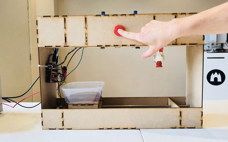 The Random Dutch Lunch Generator
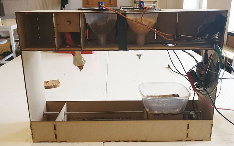 How it looks from behind
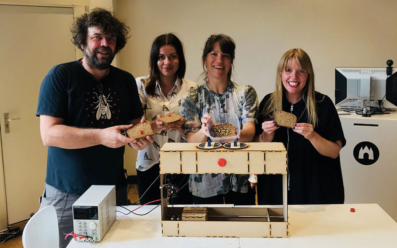 The team
What would I have made differently next time?
We have made some many versions of the stage, making it smaller, shorter, changed the top part, made it fit other parts of the machine, etc, so what I would do different next time would probably be to not make the actual shell of the machine before making sure everything works as I planned.
I would make sure we had all the components before deciding what types of functions the machine would have. Now there wasn’t enough stepper motors without an attached screw to it, which resulted in us not having the second tube topping.
Download files here
Final code for Random Dutch Lunch Generator
Stepper motor test code
Dxf-file for cutting
group assignment:
assignment: same as individual assignment
Week 17: Wildacard Week
assignment: Design and produce something with a digital fabrication process (incorporating computer-aided design and manufacturing) not covered in another assignment, documenting the requirements that your assignment meets, and including everything necessary to reproduce it. Possibilities include (but are not limited to) composites, textiles, biotechnology, robotics, and cooking.
Fun week! But wildcard week didn’t become so “wild” for me, I decided to try composite as previous years of Fab Academy. I have realized that I prefer the weeks of creating something with my hands, preferably something bigger, and also something that could be useful in my everyday life. Most often it is the time to decide what to make that proportionally takes the longest. Therefore, I decided to make something that I need. And I need a new flower pot for a plant that my sister has been taking care of while I’m here in Amsterdam.
I had a look at some work that has been done in Fab Academy before: this one and this one.
My requirements for this assignment are similar to the ones for the composite week in prior years; Design and make a 3D mold, and produce a fiber composite part in it.
Designing a flower pot
I decided that I wanted to make my mold in cardboard, creating slices that when assembled could work as my mold. Therefore, I used Fusion 360 and Slicer for Fusion 360 to create the flower pot.
Fusion 360
I made a simple shape of the flower pot, more or less a rectangle with the corners rounded by using the command “Fillet”. I also made circles on the side of the rectangle, that would, when revolved around would create a pattern. I made one circle and then I used the “Rectangular Pattern” to create more in line with the first one. When I then marked all profiles and the axis to revolve around, using the “Revolve” command, the design became a solid flower pot. I right--clicked on the body in the browser and saved as STL.
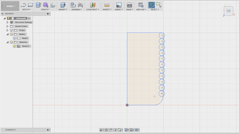 Adding circles for structure
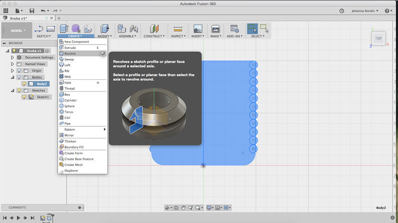 Revolve command
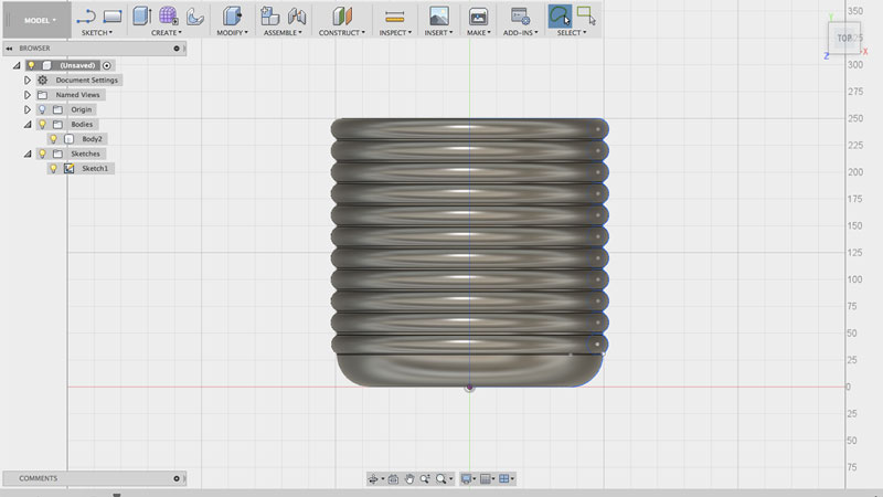 Final design in Fusion 360
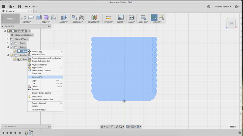 Save as STL
Slicer for Fusion 360
I have used this program a lot to make lamps in my spare time. It’s great because it helps you create slices of your design and do all calculations for slots etc. However, it has many bugs, one of them being you can’t change the material thickness in an easy way (David actually found a way to go around this) and the pdf or dxf files of the parts need some post-work in Illustrator according to me.
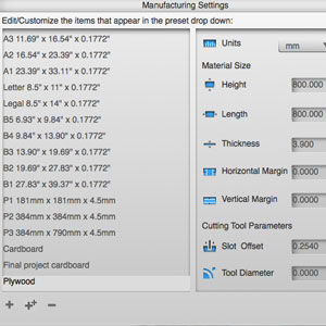
Settings in Slicer
Workflow in Slicer for Fusion 360
- Import model
- Click on the pen symbol in the “Manufacturing Settings” and create a new item. Set the material thickness, the size of the material you will cut and the offset, being the kerf.
- In “Construction Technique” click on the technique you prefer. I used “Radial Slices”.
- Set the “Slice Distribution”, deciding the number of radial and axis.
- In “Modify Form” I click “Hollow” and make it hollow the amount I want. In this case, I kept them model solid.
- Click “Get Plans” to export your file. I use PDF and then I do some post-work in Illustrator.
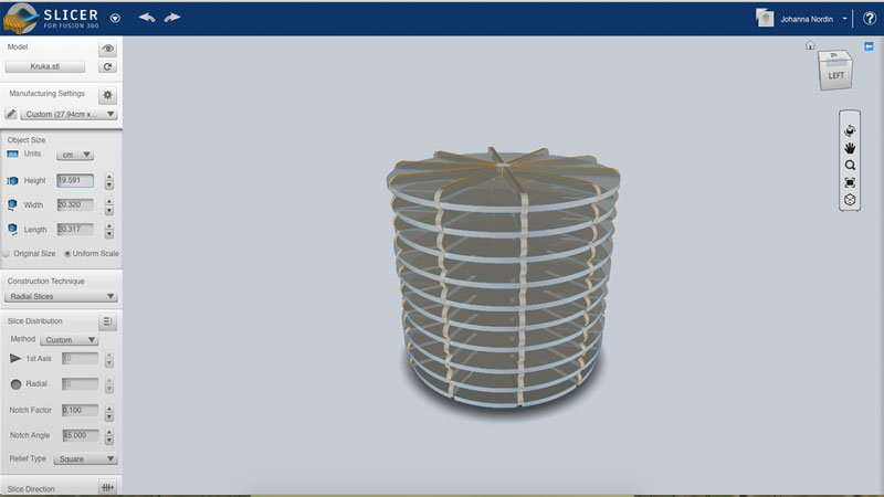 Model in Slicer
Post-work in Illustrator
In Illustrator I place the parts in a better way, that will save the amount of waste material. I also talk away the numbers for the assembling since this design is easy to understand how to assemble.
Laser cut the design
I used 3mm cardboard for my design and I followed the workflow of the week of Computer-Controlled Cutting.
3 mm cardboard
- Speed: 150
- Power: 90
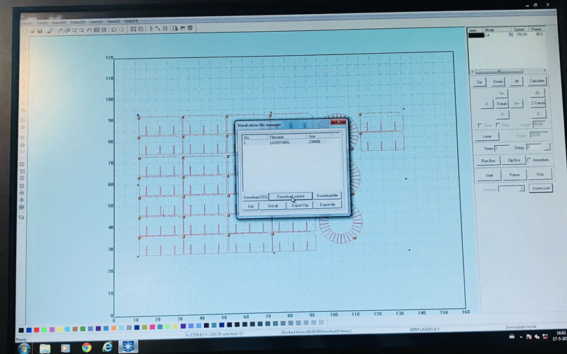 Laser cutting settings
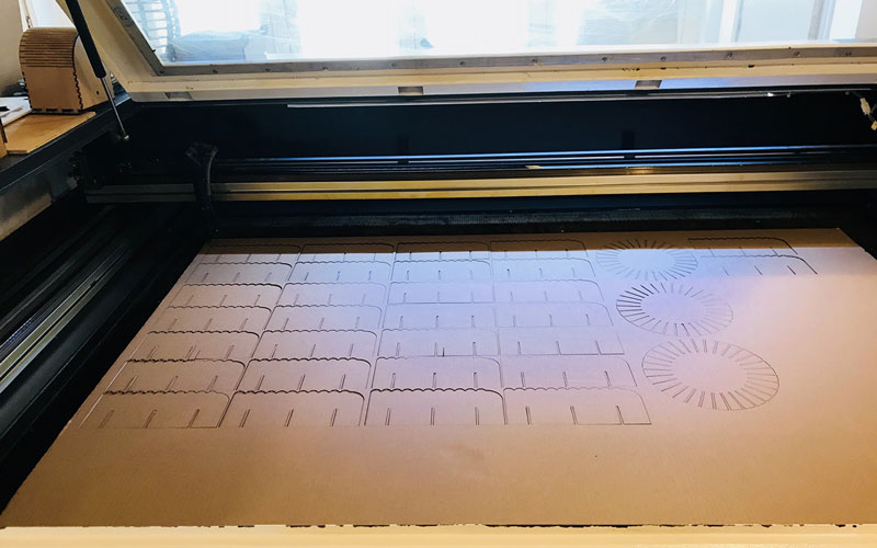 All pieces cut and ready
The cut went great and I assembled the pieces. Now my mold was ready!
Creating the flower pot of composite
Prepare for composites
If putting epoxy on cardboard, the cardboard will stick too. For that reason, I needed to prepare the mold with plastic foil and vaseline for the epoxy not to stick to my mold and easily slide off when cured.
I figured, to attach the plastic foil and to keep some of the shape of the design, “the bubbles”, some elastic bands would do the trick.
I then added vaseline on top of the plastic foil.
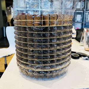 Plastic foil
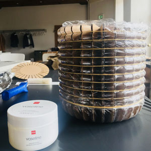 Vaseline
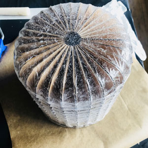 Vaseline on plastic foil
The material that I was going to use was a jute fabric that we have in the Fablab. The material was pretty thick so I decided to do only two layers. I cut the fabric in three different parts; one circle for the bottom, one long rectangle for the side, these being the base layer. And then I cut one sun-like shape to put over the base layer.
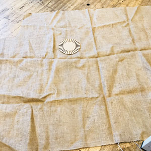 Fabric
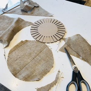 Cutting the fabric
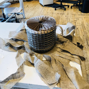 Cutting the fabric
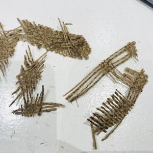 The fabric break easily
 A nice wig
Prepare the space
Epoxy is both sticky and bad to inhale and get in contact with, so preparing the space is essential for this project. My working area would be next to the open window for better ventilation. I covered the table with some big black garbage bags and made sure I had everything I would need at the table before starting; scissors, paper towels, extra protection gloves, vaseline, elastic bands, my fabric, etc.
I worn a laboratory jacket, protective gloves, and glasses and a gas mask.
Blend the epoxy
I did the blend of the epoxy in the ventilation cabinet. The epoxy that I was using is the Tarbender, High Gloss Clear Coating and Encapsulant. On the datasheet, it says that the mix ratio by volume is 2A:1B, but I decided to go for the more precise measurement and mix ratio by weight, 100A:41B. I did two batches because the data sheet also gives you an estimate of the coverage rates which make me believe that two batches would be enough. It actually turned out to be the perfect amount.
I poured part A and part B in separate cups and weigh them. When I had the right amount, I poured both of them in a bigger cup. Then I stirred for two minutes to make sure they would blend well.
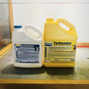 Tarbender, High Gloss Clear Coating and Encapsulant
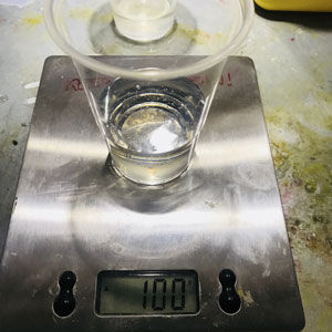 Part A
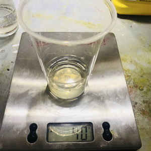 Part B
Attaching the fabric to the mold
To make sure I didn’t add too much epoxy to my fabric, I squeezed every piece before attaching it to the mold, seeing if epoxy would come out, and also making it spread better on the material. Then I attached it to the mold, having some elastic band helping it to hold.
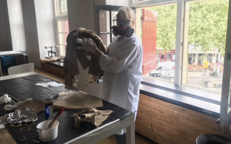 Blending epoxy and the fabric and attatching to mold
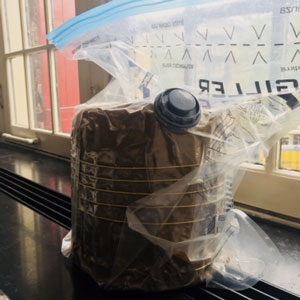
Curing in vacuum bag
Curing
For the epoxy to cure in a good way, I decided to use vacuum bagging. I put some vaseline on some baking paper and wrapped that around my flower pot full of epoxy, for it to not stick to the vacuum bag. I again used elastic bands to keep it together. I placed the flower pot inside the bag and used the regular vacuum to suck out all the air. My flower pot was ready to cure, cure time 16 hours.
The final flower pot
I left my flower pot to cure from Friday to Monday. When I on Monday took the flower pot out of the vacuum bag, I could feel it had hardened. It was a bit sticky, but that was from the vaseline. My mold was stuck in the flower pot since I had bent the edges of it a bit. Because of this, I had to tear the cardboard off.
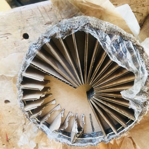 Break the mold
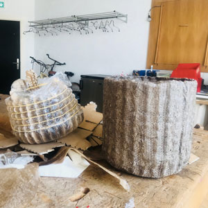 I got the mold out after some struggle
 A bit bruised after getting the mold out
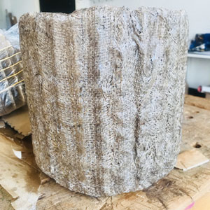 One side
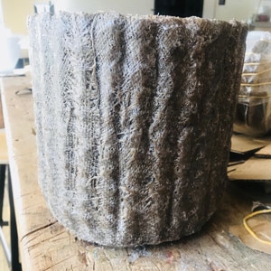 The other side
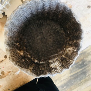 Inside
 Ta da!
I’m really happy with the result of the pot. The “bubbles” are somewhat visible, but even more is the area between each cardboard which I enhanced with pulling the material a bit extra in that middle space.
Download files here
Week 18: Applications and Implications
assignment: propose a final project that integrates the range of units covered.
What will it do?
I have made interactive cardboard cubes for my final project. Looking at it, it seems like it’s only a stack of cardboard pieces. But when you hold them or put them together, LEDs will lit up and blink in different ways depending on the action; how many you put together or what you put them close to.
The cube is a toy for kids. My sister’s two kids, Ingrid the Tiger and Ebbe the Bear, they like playing with regular building blocks, many times made out of wood. I thought I should add some features to this, making them blink, sing, vibrate, etc. This was my initial idea for my final projects; making wooden cubes that would have multiple outputs depending on the connection made between the cubes. But with the time limitation (I have to leave the Fab Lab in Amsterdam already at the end of May), I am really happy with the result, and I really like the look of “a stack of cardboard”.
I have been striving for something that looks simple, but when interacting with it, it becomes more interesting. That is also one of the reasons for choosing cardboard as my main material. I have also made sure that the cube can be taken apart and assemble again, without the use of clue, screws or similar. The reason for this, is because I want the users to be able to have a look and see how it works. The inner structure can also be placed in other shapes; spheres, cylinders, stars ect, which makes the design flexible and exploitative.
The cardboard cube is 8x8x8 cm, and it has 8 neodymium magnets in each corner. Inside the cube, there is a 3D printed 5x5x5 cm inner structure. The inner structure is holding a PCB in the middle of the cube. The cube runs on a 3V coin battery placed on the backside of the board. My input device is two capacitor sensor, connected to vinyl cut copper foil that is designed to fit the 3D printed inner structure. The output is the 6 LEDs using the charlieplexing technique to fit all the LEDs with the number of pins on the ATtiny84.
Who's done what beforehand?
Neil says “Stand on the shoulders of giants”, meaning we should learn from what others have done and made something better. I have been standing on my own shoulders during this project and it's been more than I can handle at this point and with the time limit. I have seen many interactive cubes before, many made at the Fab Academy, see list below. And I have seen a great number of interactive toys for kids, many that are very fun and complex, and some really exploitative and useful in learning. My cube is far from as interesting, fun, or developing as many of these. I, however, like that mine is made out of cardboard; an affordable and creative material. I also like that the parts can be taken apart and be assembled again.
Inspiration:
- Johanna Okerlund from Fab Academy 2017, made a set of blocks, that when connecting them to each other, and pressing a button on the computer, a poem was created.
- Takuma Oami from Fab Academy 2014, made building blocks that can be exported to PC as 3D model.
- Dana Schwimmer from Fab Academy 2014 made sound cubes.
- AutomaTiles has made some really nice looking hexagons that can connect in on all sides - and do many more things
- Cubelets Robot Blocks - robot-like cubes with many different inputs and outputs. Very good for kids exploration.
- Magna Tiles - kids toy for construction of shapes with magnets being able to connect on all sides.
I have designed and made all the parts of the interactive cardboard cube (except from the magnets and the components on the board. I have done the schematic and board design in Eagle, vinyl cut the copper foil designed in Illustrator, laser cut the cardboard, made in Fusion 360 and Slicer for Fusion 360. I have also 3D printed the inner structure which is also designed in Fusion 360.
I have incorporated all the requirements for the final project.
- 2D and 3D design - in Fusion 360, Slicer for Fusion 360, and in Adobe Illustrator
- additive and subtractive fabrication processes - Additive by using the 3D printer and subtractive by using the laser cutter, the vinyl cutter and the small CNC milling machine for making the board.
- electronics design and production - creating the schematic, designing the board, milling the board, solder on components
- microcontroller interfacing and programming - programming the board in Arduino IDE using C.
- system integration and packaging - I have designed my cube so that all parts fit nicely together. I have used the square centimeters in effective way, not leaving any space unused. Except from the LEDs on the top and the bottom, there is no wires to connect the pieces. The cube is ready to use, and even if we’re not used to a “stack of cardboard pieces”, this cube is ready to be played with!
What materials and components will be used?
Components on the PCB:
- ATtiny84
- 6 pin header
- 4 pin header x2
- Capacitor 1uf
- Resonator 20 mhz
- Resistor 0 ohm x3
- Resistor 499 ohm x3 (might change depending on LEDs)
- Resistor 10k ohm x1
- Resistor 10M ohm x2 (might change depending on capacitors when inside cube)
- 2032 battery holder
- CR2032 Lithium battery 3V
- LED (through hole) 6x
- Wires
- Soldered on to a one-sided copper plate
Material:
- Cardboard, 8x8x29 cm
- PLA 0,4 mm, approx 50 cm
- Cube magnets, neodymium, 5mm, 8
- Copper foil, 5x5x15x2 cm
How much will it cost and where do you buy it?
All my components and material can be found in the Fab Lab. Fab Lab buys them from electronic resellers in China or from Digi-Key. The magnets and the battery makes up more than half the cost of the cube. The components and the material all cost less if you buy more than just one, making these costs at the highest level.
Cost per cube:
- Cardboard: € 0,98 (4,90 for a piece fitting 5 cubes)
- PLA:
- Cube Magnets: € 3.04 (0.38 €/magnet)
- Copper foil:
- Components:
- ATtiny84: € 0,58
- 6 pin header: € 0,24
- 4 pin header x2
- Capacitor 1uf
- Resonator 20mhz
- Resistor 0 ohm 3x
- Resistor 499 ohm x3 (might change)
- Resistor 10k ohm x1
- Resistor 10M ohm x2
- 2032 battery holder
- CR2032 Lithium battery 3V: 2,95 €
- LED (through hole) 6x
- Wires
- Soldered on to a one-sided copper plate
- Time: :)
- Total: around 10 €
How will it be evaluated?
My interactive cube should be evaluated on the creativeness of the simple design, making a cube that can be taken apart and reassembled. This creates possibilities in making other shapes, and also exploring the different components inside the cube.
It can also be evaluated on the consideration of designing and making all parts, and making them from cheap material, resulting in a very affordable cube.
It should of course be evaluated on the performance of the input and the output. Since none of these are that special, I want it to be evaluated on the first and second impression; first just seeing the stack of cardboards, to then hold it and put it together with other cubes, and then taking it apart to look inside - was it what you had expected?
My own concern and thoughts
Oh, there are many thing that I would do differently if I had more time. The biggest thing would be to make more outputs. At this point, my cube isn’t that interesting, it’s just LEDs blinking in different ways, and I would have liked it to be more fun. Also with different outputs, maybe on different sides of the cube, it would have been more explorative for the kid.
If I had more time I would redo the board, making it look better. I really like making the board as small as possible and also good-looking. I also made the holes for the battery holder a bit too big, I could just have made the holes small enough for a regular wire.
Right now I haven’t figured out how to attach the pieces together. I have holes for a stick to be placed, but it will be important to attach the first and the last one really hard so that the magnets do not open up the cube.
Next steps
- 3D print one more inner structure
- Attach copper foil to inner structure
- Solder two more boards
- Program all three boards with final code
- Test the cubes together and calibrate the sensors
- Find out a way to put the pieces together + eventual design and make that piece
- Write documentation
- Make video
I’m almost there!
Week 19: Invention, Intellectual Property, and Income
assignment: develop a plan for dissemination of your final project
This week’s assignment is about how I plan to disseminate or spread and promote, my final project to a wider audience. It is also about the associated property rights and what sort of advantage or profit I will gain from it.
Licenses
Since my final product isn’t rocket science and not very innovative, I have no plans of licensing it or disseminating it further than just the final presentation and then apply my learnings to projects that I’ll do in the future.
Furthermore, I have no plans of claiming any intellectual property rights. Wikipedia explains it well; Intellectual property (IP) is a category of property that includes intangible creations of the human intellect, and primarily encompasses copyrights, patents, and trademarks.
If anyone, at any time, wants to add on to my final project or use it as it is, I would be honored and happy. One could say that I’m applying a version of an open source license in which I give others the rights to study, change, and distribute my final project to anyone and for any purpose. This is also in line with the Fab Labs that adopt a sharing model where everything is made available for others to learn from.
Even though I'm not planning to claim any rights or licensing my final project, I did find one licens that I liked and could use another time. On Creative Commons website you can read about how they help to legally share knowledge and creativity. They so this to build a more equitable, accessible, and innovative world which is inline with my values. Creative Commons offer free, easy-to-use copyright licenses. They provide a simple, standardized way to give permission to share and use creative work.
The license I would use is the "Attribution 4.0 International" which they recommend when going through their website and selecting the options you would like for your license. The license says "You are free to: Share — copy and redistribute the material in any medium or format. Adapt — remix, transform, and build upon the material for any purpose, even commercially. This license is acceptable for Free Cultural Works. The licensor cannot revoke these freedoms as long as you follow the license terms." It continues "Under the following terms:Attribution — You must give appropriate credit, provide a link to the license, and indicate if changes were made. You may do so in any reasonable manner, but not in any way that suggests the licensor endorses you or your use. No additional restrictions — You may not apply legal terms or technological measures that legally restrict others from doing anything the license permits."
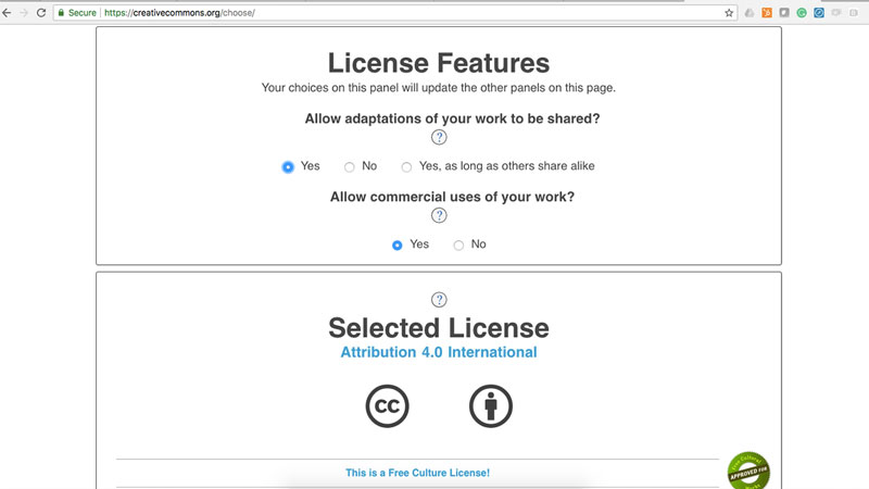 Selecting the attributes of the licens
 Attribution 4.0 International
Income generation
My intention is not to make money on my final project. The main gain of it was to learn from and explore. That I have succeeded with.
Week 20: Project Development
assignment: complete your final project, tracking your progress
Most of this documentation could be found under the Final Project page.
What tasks have been completed, and what tasks remain?
When I left to go home to Sweden, during the last week, I was mostly done will all the different parts of the cube. I had to figure out a way to attach the pieces together. In Sweden, I designed and printed the rods and caps. Back in Amsterdam for final presentation, I did the final calibration of the capacitive sensors.
What is the deadline?
The deadline for the final project is 20th of June when I present to all the other students.
How will I complete the remaining tasks in time?
I have planned the different tasks well so I would complete everything in time. If I would have more time, I would redesign the board and keep only one sensor that would ease the calibration, which has taken the longest time due to the unstableness of capacitive sensors.
What has worked? What hasn't?
Everything has worked fine. Like mentioned, it's been some troubles with the capacitive sensors since the normal condition change depending on what cables are attached to the board, how close it is to the computer, is the battery is attached etc, which made that part really hard and time-consuming. It was hard to find a threshold that was correct at all times.
What questions need to be resolved?
If I were to do this project again, I would re-think the input device. Capacitive sensors are not the most stable and easy to calibrate. So I guess the question is - which input device should I use?
What have you learned?
I have learned so many things. I integrated most of the processes and methods that we learned during Fab Academy. But mostly I have learned things about myself; how I function under stress, what I like exploring, what I don't like as much, how much I'm capable of, and that I could possibly make (almost) anything.
'